The Handlebar Stem for a Road Bike - SPORTS & STEMGEEKS FOCUS
- - - All Rights Reserved - - -
Hello everyone!
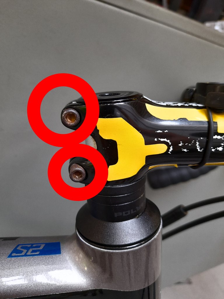
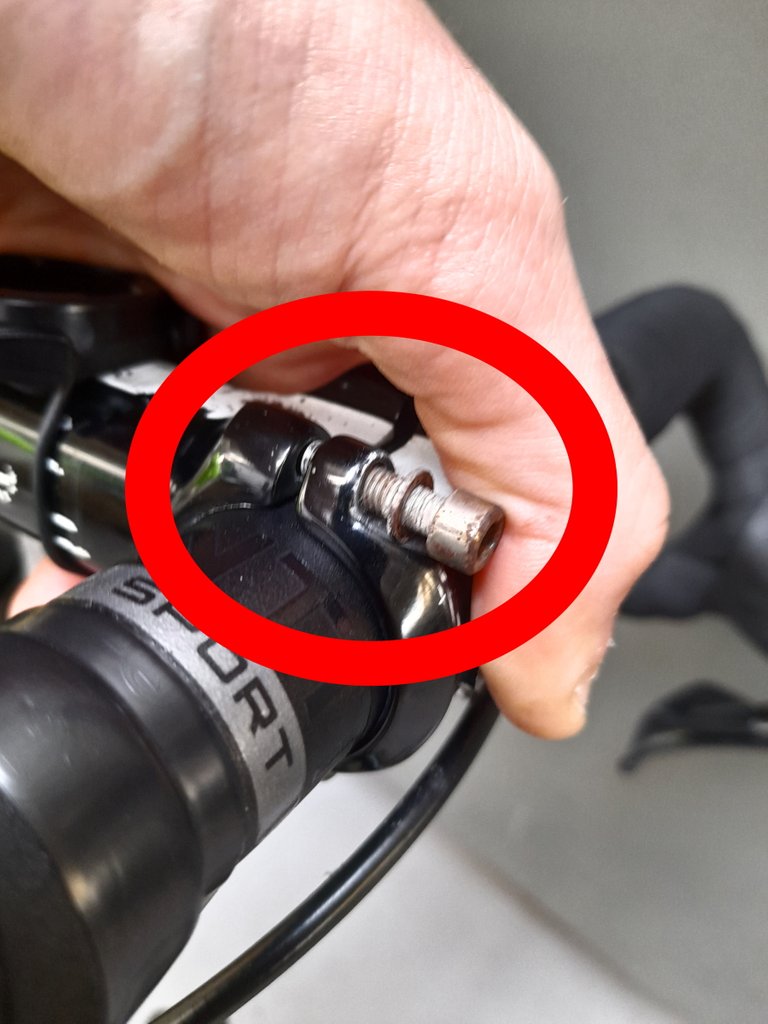
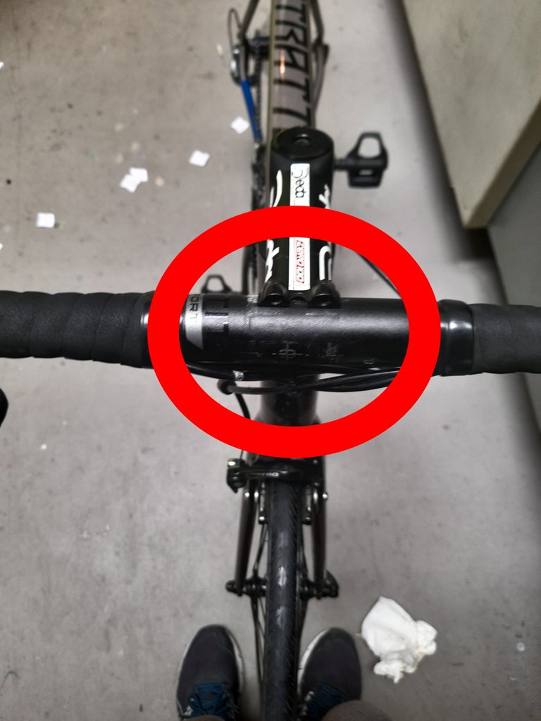
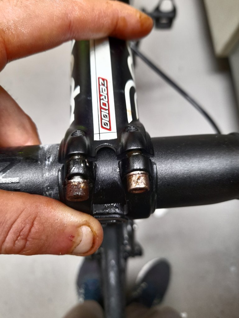
Today I will show step by step how to disassemble and reassemble a fundamental part of a racing bike, known as a stem handlebar. This portion allows you to connect the real handlebar of a bike to the tube connected to the fork. In the photo below you can better understand what I'm talking about, you can find the object inside the red circle.
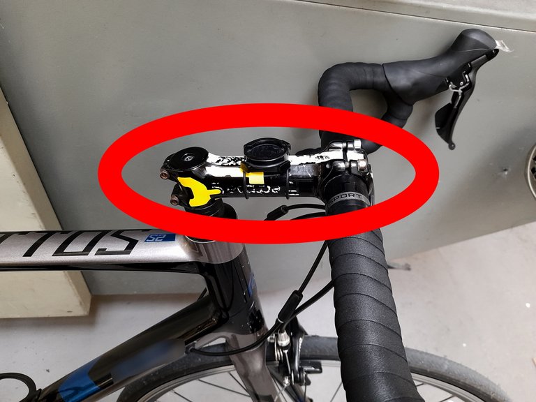
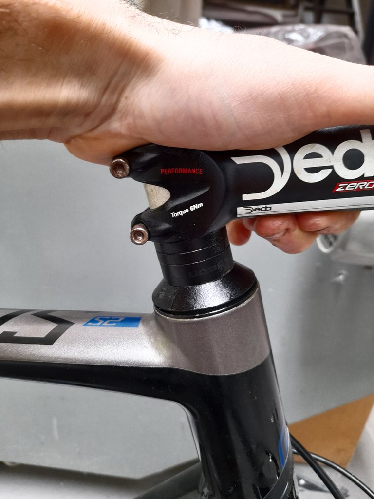
The handlebar stem is usually formed by a horizontal component of various lengths and by two ends that are fixed one to the handlebar, the other to the fork tube. The length of the horizontal component allows you to differentiate various types of the stem, which are measured through the total length in millimeters. For example, let's talk about stem size 90, 100, 110, etc.
The front terminal is formed by a fixed component and a kind of cover, which can be fixed through the use of some screws that have a wider head used to receive an Allen screw, thanks to which it will be possible to fix the cover.
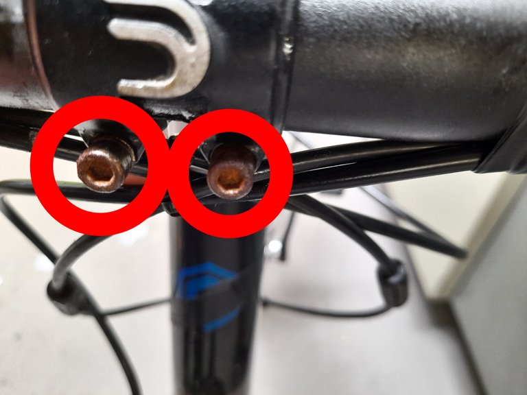
The back terminal is instead fixed and has a useful width to receive the fork tube, slightly wider than the diameter of the tube itself. Once inserted on the tube, just fix it by tightening the pair of screws you see circled in red in the figure.
A further distinction in the type of attack is the angle they are equipped with: it is important to compensate for the angle of the fork tube with respect to a hypothetical vertical axis. This ultimately allows you to raise or lower the height of the handlebar relative to the ground.
But let's go into detail: how to disassemble and reassemble our handlebar stem?
DISASSEMBLY
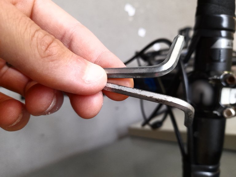
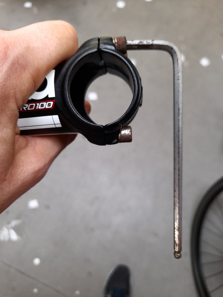
To remove the stem it is necessary to use appropriate Allen screws or wrenches, usually hexagonal. Depending on the manufacturing company, the hex keys may vary.
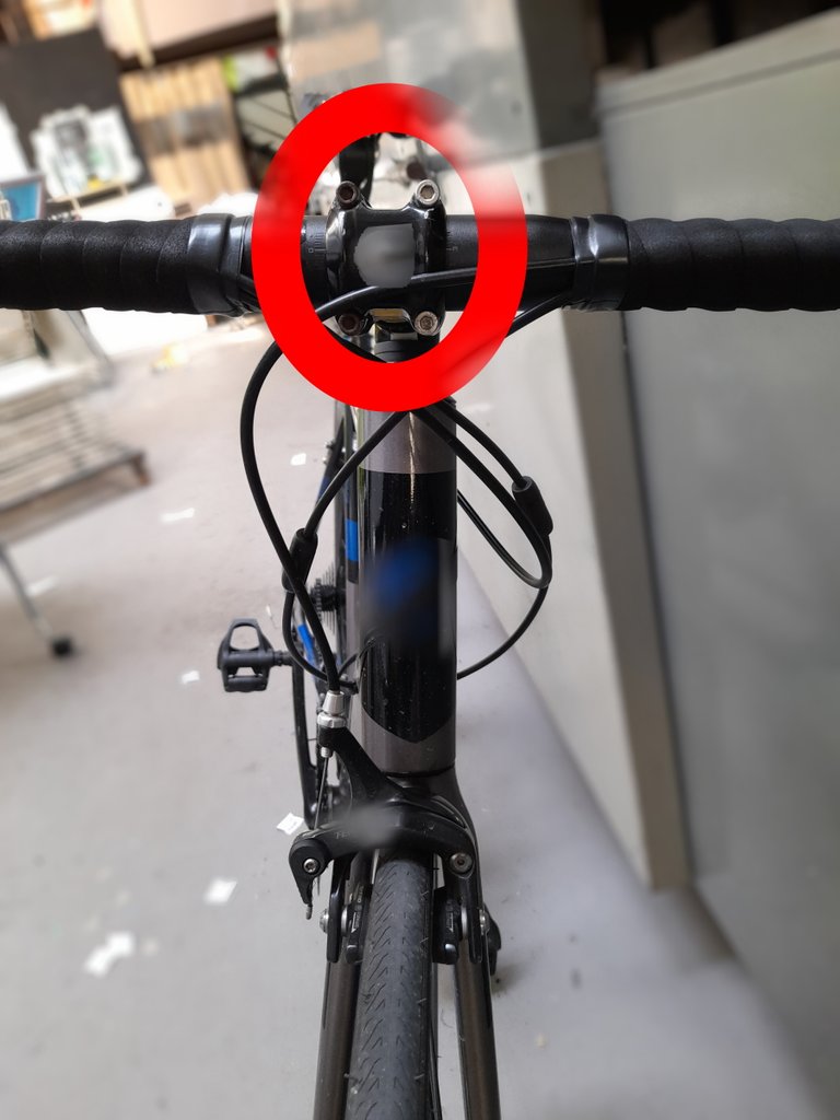
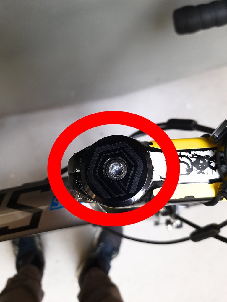
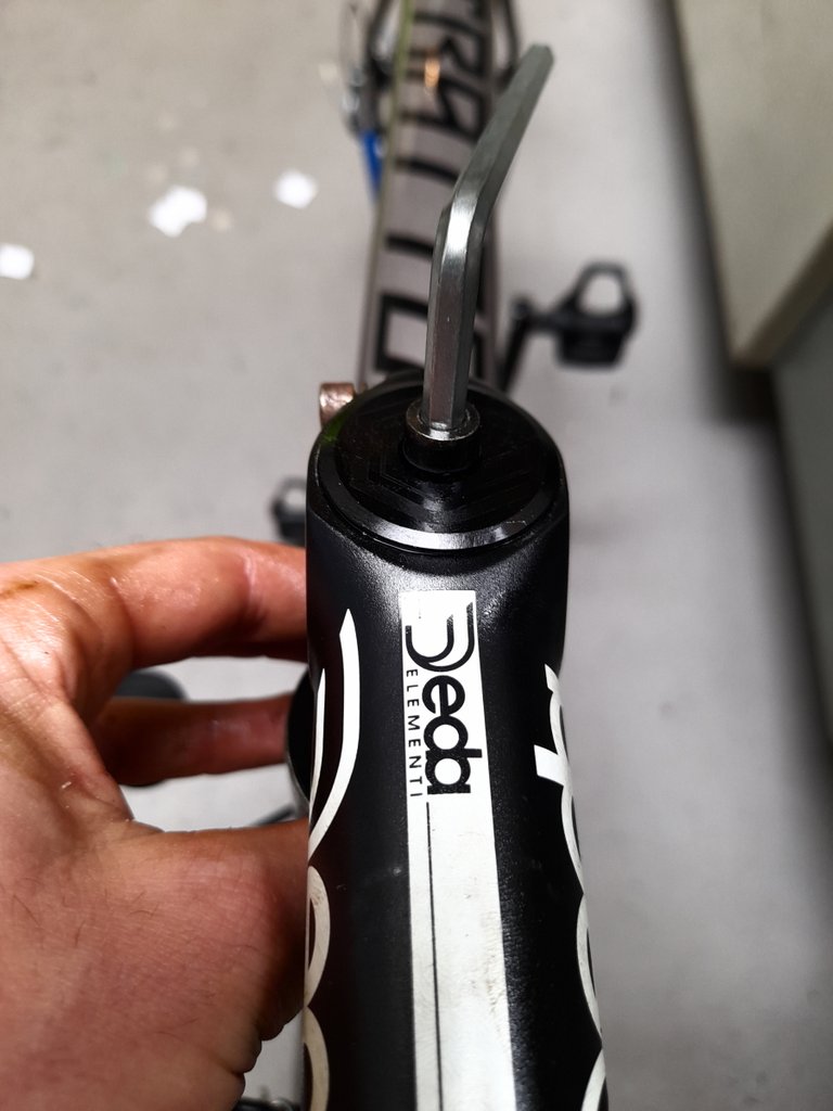
The first step is to loosen both the pair of screws on the rear terminal and the screws on the front one. But this is not enough: it is also necessary to loosen the grip of a small cover that is fixed above the rear part of the stem, so as to fix and make the various parts connected to the fork tube more stable. You can see this cover circled in the figure below, along with the 2 screws to loosen on the rear of the stem.
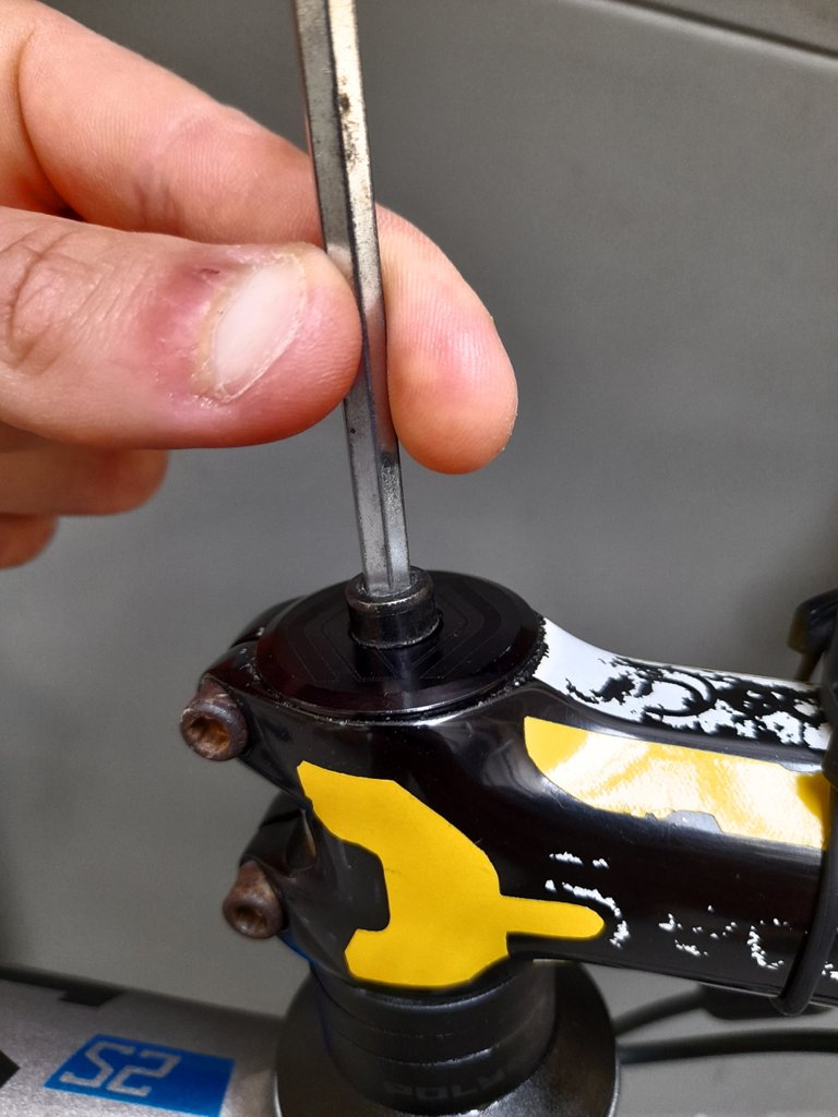
I inserted the appropriate hex wrench and started unscrewing until the cover was removed. In the following photo, you can see the inside of the upper end of the fork tube, in my case to clean up a little.

I then loosened the screws on the rear end and switched to those on the rear end, again with the appropriate cover.
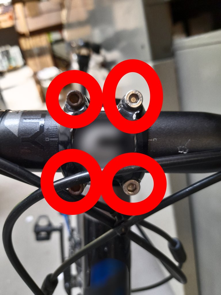
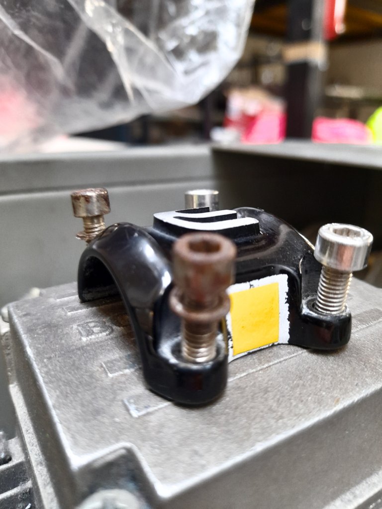
Once all the 4 front screws have been unscrewed, I removed the cover - which you see immediately below resting on the shelf - and I removed the handlebar.
Right after that, I grabbed the rear end and pulled off the stem.
PAY ATTENTION:
both under and above the stem there are usually shims. To keep the bike measurements unchanged, the shims must be repositioned in the same position. In my case, I only had shims below the stem.
DOUBLE ATTENTION:
under the stem there are bearings and blocks that allow you to avoid wear or displacement of the fork tube (and of the fork itself). It is essential that they are not moved for any reason other than by more expert hands. If so, they may no longer perform their function, leading to serious safety problems as well as operational problems.
REASSEMBLY
We left our fork tube uncovered. Now we can reassemble the new stem. In my case, I reassembled a 1 cm shorter stem, going from a 120 to a 110 one. To begin, we loosen the screws on the front cover of the binding, until we can remove it.
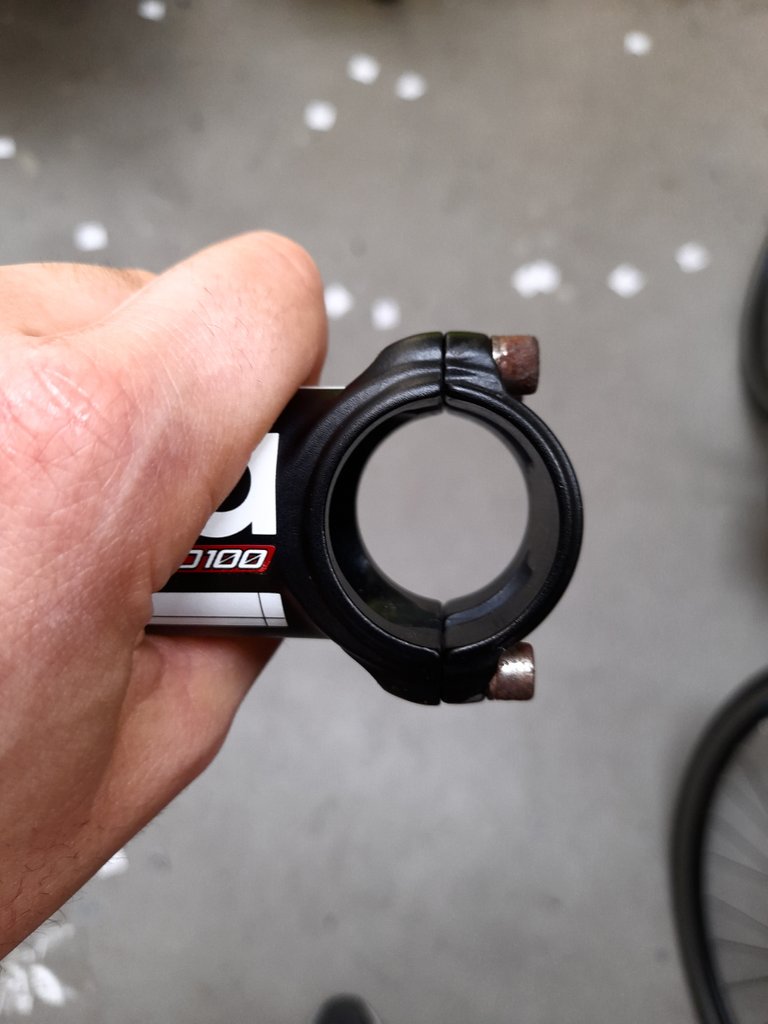
At this point, we also loosen the rear screws and insert the stem on the fork tube, as shown in the figure. Let's cover the tube with the cap we saw in the previous paragraph, so as to cover the fork tube. In my case, you can see brownish-red fingers because I decided to apply a little lube before tightening everything.
We must not be in a hurry to tighten the screw: the cover is fixed, but it must leave free the stem to any movements since at this stage it is not yet centered as it should.
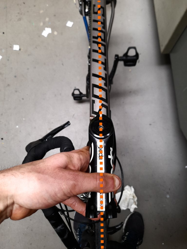
We must in fact make sure that the stem is perfectly in line with the straight line passing through the perfect half of both the rear wheel and the front wheel. In the figure, you can see it dashed.
Tighten the screws well: start with the one on the upper cover and then move on to those on the rear end of the stem. Each screw or pair of screws has its own ideal strength for tightening. Always be sure to follow the instructions given by the manufacturer of the object.
At this point, we insert the handlebar inside the recess formed by the front terminal. Again, recommended to lightly lubricate. We then begin to insert the screws and reattach the front cover, so that the handlebar is no longer able to come out of its housing.
It starts with the upper screws and then moves on to the lower ones. ATTENTION: if the cover is not perfectly symmetrical, you must make sure that the direction is the right one and not fixing it upside down.
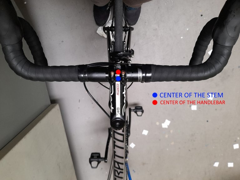
Done, the handlebar is in place. Unfortunately, that's not all: the handlebar must also be perfectly (or almost) centered on the frontal plane. That is, the center of the handlebar must fall into the center of the stem, except in special cases (handlebar stems with a particular design or postural asymmetries of the cyclist who is going to ride).
Just this? No, after inserting the handlebar in the right position, we tighten the screws and the front cover a little more, so that the handlebar does not move by itself. However, we must leave a space of movement for the last adjustment of the day: the adjustment on the horizontal plane, the one visible if we look at our bike from the side. In the figure, you will find what I mean, and you can see a dotted line that corresponds to a line parallel to the ground.
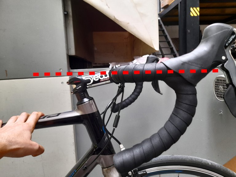
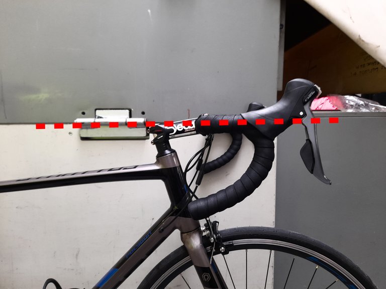
Here are diversities depending on your needs. In case you don't have specifics to start with, you can try a few. In the case, in the figure, I kept the parallel to the ground parallel to the first lateral portion of the handlebar. However, if we go further we see that the rubber cover of the handlebar that precedes the brake rises upwards: this is the reason why many prefer to lower the handlebar further and make sure that the parallel to the ground corresponds to the upper edge of the first portion of the gum margin.
In the latter way, we will have a lower riding position, certainly more aerodynamic. However, this will not always be the best position, especially with a very pronounced saddle height.
We finish tightening the screws according to the forces defined in the instructions and try our bike.
AND WE ARE AT THE END
But I finish by pointing out that this article and all of its content is for informational purposes only. Each procedure described here or any variant of it will certainly be carried out more carefully by qualified personnel. Furthermore, the clamping forces must be surgically evaluated: I have had experience with manual tightening that caused the handlebar to bend on several occasions following stresses not enough to cause it.
There is a place very near me called the "Newark Bike Project." It is a registered non-profit and is designed specifically to help teach people how to keep care of and maintain their bikes; I've learned a lot from them. Do you have anything like that near you? I suspect you have a lot of knowledge you could share.
I don't know of a project like the one you talk about, near me. I am not a bike expert, I only collect the advice of the bike centers that I usually turn to for repairs and I have accumulated some experience relying on mechanics tutorials that can be found on the web. Several of them share videos on youtube, for example. The difference is that there is no "a to z" tutorial, but you need to know what you want to achieve and do a targeted search. I congratulate "from afar" on the project you told me about, it is important to get to know the bike better for those who use it frequently. !BEER !PIZZA
@wwwiebe! I sent you a slice of $PIZZA on behalf of @davidesimoncini.
Learn more about $PIZZA Token at hive.pizza (1/10)
View or trade
BEER.Hey @wwwiebe, here is a little bit of
BEERfrom @davidesimoncini for you. Enjoy it!Learn how to earn FREE BEER each day by staking your
BEER.