Industrial Power System Configuration - Main Tie Main
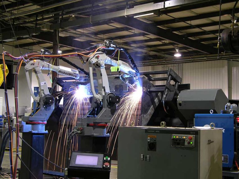
Industrial power systems can become very complex, and the related processes need a reliable source of electricity to keep the process running, both for economic and safety reasons. There are many different kinds of distribution systems. This article will only focus on one of them: the Main-Tie-Main system configuration.
Industrial Power System Main-Tie-Main Configuration
Main-Tie-Main, also formally referred to as a "secondary selective system" consists of two independent circuits connected together at the load buses by a tie breaker. See the figure below for details.
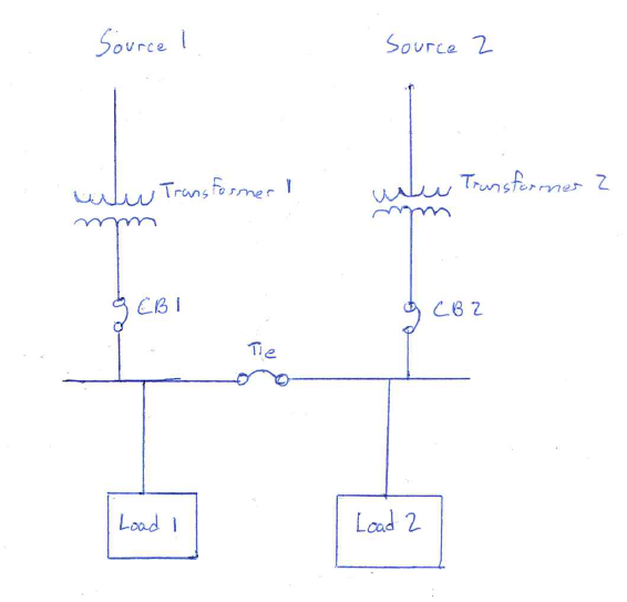
A simple main-tie-main system configuration
Reliability
The biggest advantage that a for an industrial power system that a main-tie-main configuration has over other system configurations is reliability. Usually, the tie breaker is normally open and the system acts as two independent circuits supplied by two independent sources. For example, we will assume that there is a fault on Source 2. This fault trips CB2, cutting off all power to Load 2. Immediately after power is removed from Load 2, the Tie Breaker closes. Source 1 is now providing power to both Load 1 and Load 2, and the system is able to perform its normal functions until the fault at Source 2 is repaired. When normal power is restored and CB2 is closed, the Tie breaker opens and the system resumes normal operation. Operation is only interrupted for a very brief moment, if it is interrupted at all!
The Main-Tie-Main configuration is also good for maintenance for this very same reason: you can open CB2 and perform repairs upstream from Load 2 de-energized, while still supplying Load 2 with power.
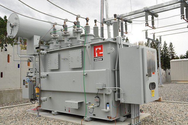
Transformer Sizing
One characteristic of the industrial power system main-tie-main configuration is that both transformers must be sized to appropriately handle the load of both buses. In our example, we will assume that both Load 1 and Load 2 are the same size. Transformer 1 and Transformer 2 must each be sized so that in normal operation they are only loaded to 50%. This way when the tie breaker closes, the transformer that is now supplying both loads doesn't become overloaded and blow up in your face. The downside to main-tie-main is that the added reliability inherently costs more due to the system requiring larger transformers than a system that would not tie both circuits together.
Unfortunately, reliability costs money, and you'll need to oversize your transformers to add reliability to your system in a main-tie-main configuration.
You can also reduce strain on each individual transformer when it is supplying both loads by adding external cooling to the transformers (like a fan cooling system). You can also simply accept that the transformers will have a reduced life in the event of a fault on a transformer or source.
You will not have just two loads in every case. In systems with multiple loads supplied by a single transformer, transformer size (and therefore cost) can be reduced by designing the system so that only essential operational loads (such as emergency lighting) are supplied power when the tie breaker closes.
Summary
For industrial power systems, a main-tie-main configuration is an extremely reliable power system distribution model, able to maintain power during a fault with little to no interruption. Unfortunately, this added reliability has a cost, whether in the form of larger transformers, extra cooling systems, or shorter transformer lifespans. These factors should all be considered when designing an industrial power system with main-tie-main in mind.
As always, thanks for reading! If you like this post but want some actionable advice, tips and information, check out our newsletter. You can sign up here or below. By signing up you get a free report on what an Electrical Safety Program is, and how to go about building one at your facility.
If you like this article and want to hear more sign up for our newsletter at jmkengineering.com/newsletter
0
0
0.000
And here am I thinking that they are all the same.
!discovery 30
No at all, in fact this is just the "typical" configurations. Today there are more and more that are adding #microgrid components to the system. This may be added generation to one or two of the buses that can either take the entire load, or just a portion of the load.
The microgrid component would include CHP plants using waste heat, renewables, diesel, etc.
This post was shared and voted inside the discord by the curators team of discovery-it
Join our community! hive-193212
Discovery-it is also a Witness, vote for us here
Congratulations @jmkengineering! You have completed the following achievement on the Hive blockchain and have been rewarded with new badge(s) :
You can view your badges on your board And compare to others on the Ranking
If you no longer want to receive notifications, reply to this comment with the word
STOPTo support your work, I also upvoted your post!
Do not miss the last post from @hivebuzz: