How to make a snake game on arduino
In this tutorial, we will learn how to make a simple game the popular snake game on the Nokia 5110 LCD and push buttons to play the game, how to program Arduino on desktop IDE and how to connect the components with a circuit diagram.
Required Components
We need this couples of requirements in this tutorial
- Nokia 5110 LCD display
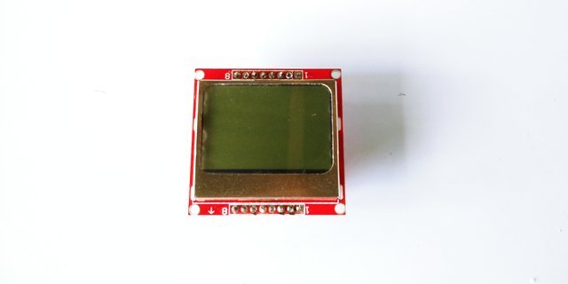
These displays were used in old Nokia 5110/3310 cell phones. It is an 84x48 pixel monochrome LCD display. These displays are small, but very readable and come with backlight. This display is made of 84x48 individual pixels, so you can use it for graphics, text or bitmaps. so less expensive than using OLED display. I bought mine for just $5 when I was in college.
- Buttons
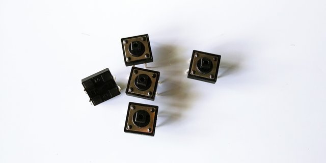
I use the Momentary Push Button Switch a 12mm Square, These buttons give a nice soft click every time it's pressed so you know that you've definitely activated it. Their almost instant return makes them great for building your own homemade button pad. it also makes a good reset switch or user feedback for a microcontroller circuit.
- Buzzer

This electric buzzer can be driven by an oscillating electronic circuit or other audio signal source. A click, beep or ring can indicate that a button has been pressed most of this user to make alarm tune or alarm system that we will use in this tutorial.
- Arduino Uno R3 board
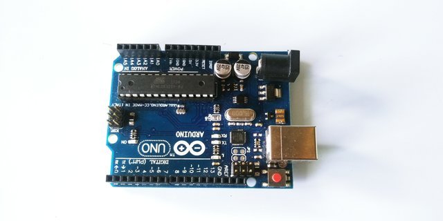
In this tutorial I am using the clone Arduino r3 board, It has 14 digital input/output pins (of which 6 can be used as PWM outputs), 6 analog inputs, a 16 MHz quartz crystal, a USB connection, a power jack, an ICSP header, and a reset button. It contains everything needed to support the microcontroller components.
- Jumper wires
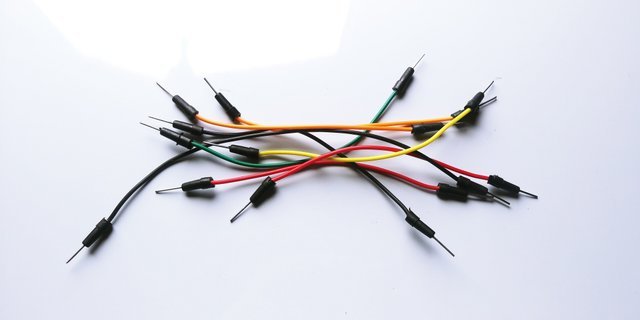
Use jumpers to connect on a breadboard or female header connector, size, and color to distinguish the different working signals. we will use the male to male jumper for 7 segment and the buttons to connect to Arduino.
- Breadboard
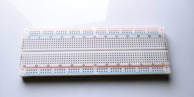
Use a Single Panel Breadboard it is a solderless device for a temporary prototype with electronics and test circuit designs. both side of the breadboard is the power rail it is horizontal lining and the middle is the vertical rail for Arduino components.
Difficulty
- Intermediate
Tutorial Contents
- SOFTWARE
we are going to use the Arduino ide, to set the sketch for this, if you don't have to make sure to download the Arduino IDE for your specific operating system. I’ll leave a link to where you can download this software: https://www.arduino.cc/en/Main/Software
- Libraries
To run the program and to make sketching a code easily we need to download these couples of libraries. Adafruit-GFX-Library; https://github.com/adafruit/Adafruit-GFX-LibraryAdafruit-PCD8544-Nokia-5110-LCD-library; https://github.com/adafruit/Adafruit-PCD8544-Nokia-5110-LCD-library/
- Nokia 5110 CIRCUIT DIAGRAM
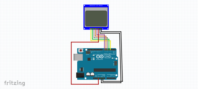
To drive the Nokia display, we need 5 digital output pins. the LIGHT pin can be used to control (via on/off or PWM) the backlight, the GND and the LIGht pin should be connected to GND on the Arduino board, The display driver is a PCD8544 chip which is on the library we've recently downloaded, and it runs at 3.3V so you will need a 3V supply handy. Logic levels must be 3.3V to prevent damage so you must use some kind of resistance. or we can use a resistor between the light pin and the GND pin on the Arduino. the remaining pin on the LCD will be connected to the specified digital pinout on the Arduino board listed below.
- pin 7 - Serial clock out (SCLK)
- pin 6 - Serial data out (DIN)
- pin 5 - Data/Command select (D/C)
- pin 4 - LCD chip select (CS)
- pin 3 - LCD reset (RST)
Push Buttons CIRCUIT DIAGRAM
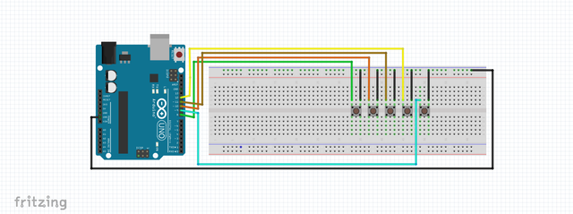
The pushbuttons has 4 sets of legs but we will use 2 legs, both the right leg is connected to the GND pin on the Arduino, the left one is connected to the specified Arduino pin depends on the use of it. we will use 5 buttons the 4 is the navigation buttons and the 1 is for the pause button.
- button 1 LEFT - 8 pin on Arduino
- button 2 DOWN - pin 10
- button 3 RIGHT - 11
- button 4 UP - 12
- button 5 PAUSE - 9
Buzzer Diagram
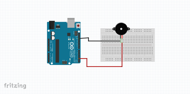
The buzzer has 2 legs the GND supposed to be the short leg of the buzzer and the long leg is connected to the Digital pin on the Arduino. we will use these button as a ringtone every time the snake eat the egg it's beeping.
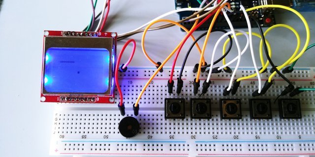
- Combine all the components in one breadboard
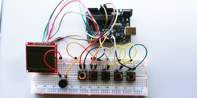
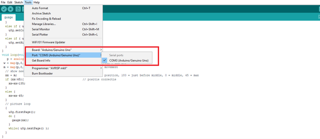
Connect the Arduino UNO board to your computer using the Type B USB cable included in the package. open the Arduino Desktop IDE locate the TOOLS verify the type of board you are using PORT should be on the COM# and the board should be on the Arduino/genuino uno if you're using the same board as mine.
- Programming a code
Include the libraries we've recently downloaded, the EEPROM.h is already on the Arduino library.
#include <EEPROM.h>


#include <Adafruit_GFX.h>


#include <Adafruit_PCD8544.h>
Define the pin output of the Nokia LCD
Adafruit_PCD8544 display = Adafruit_PCD8544(7, 6, 5, 4, 3);


// pin 7 - Serial clock out (SCLK)


// pin 6 - Serial data out (DIN)


// pin 5 - Data/Command select (D/C)


// pin 4 - LCD chip select (CS)


// pin 3 - LCD reset (RST)
Define the pushbuttons pin output
#define LEFT 8


#define DOWN 10


#define RIGHT 11


#define UP 12


#define PAUSE 9


#define MAX_WIDTH 84


#define MAX_HEIGHT 48


#define speakerPin 2
Direction of the snake that is currently moving
boolean dl=false,dr=false,du=false,dd=false;


int x[200],y[200],i,slength,tempx=10,tempy=10,xx,yy;


unsigned int high;


uint8_t bh,bl;


int xegg,yegg;


int freq,tb;


int l,r,u,d,p;


unsigned long time=280,beeptime=50;


int score=0,flag=0;
setup() method is run once at the just after the Arduino is powered up and the loop() method is ran continuously afterward.
setup() is where you want to do any initialization steps, and in loop() you want to run the code you want to run over and over again.
Download code HERE

I hope you enjoy this activity if you want to learn how Arduino works, and how to make a sketch, then maybe this site http://educ8s.tv/ might help you, and Abhinav Fauzdar since I'm always following their project for this stuff, all images on this blog are supposedly mine that I posted a year ago you can find the original post from this link. thank you for stopping by.