Arduino | Color oled running on Adafruit SSD1331 Library
Everyone can give life to electronic gadgets on their own do it your self projects. building own creative toys, a weather station, mini arcade games, play music, make an Led blinking chaser which involved hard electronics and software skills. Arduino helps us to understand the concepts of electronics and develop the software. For this tutorial, I will be using the Arduino r3 and the colored OLED module running on adafruit OLED library. this colored OLED is much better than the other OLED which has only 2 color B&W, This module can support up to 65 thousand types of colors which is perfect for making animation and on-screen activity.
Repository
For more information about the version of Arduino please visit the following GitHub repository link which include the installation process of the software:
https://github.com/arduino/Arduino
What Will I Learn?
This tutorial, you will learn the following.
You will learn the basic programming skill of Arduino
You will learn how to connect electronic modules to Arduino
You will learn how to display text and color to OLED display
Requirements
For this part, we need these following Arduino components.
0.95-inch color OLED Display
Arduino Microcontroller board
Jumper wires
Breadboard
Difficulty
Basic
The Uno is a great choice for your first Arduino. It’s got everything you need to get started, and nothing you don’t. It has 14 digital input/output pins (of which 6 can be used as PWM outputs), 6 analog inputs, a USB connection, a power jack, a reset button and more. It contains everything needed to support the microcontroller; simply connect it to a computer with a USB cable or power it with an AC-to-DC adapter or battery to get started. reference
Tutorial Contents
This tutorial contains the following:
Introduction of Arduino software IDE
INCLUDE Adafruit-SSD1331 Library to IDE
DEFINE the Colours Code for the OLED
Build the code| Declare and include function of the sketch
Initialization of SETUP and LOOP() Function
Building the Circuit
Upload Sketch to Arduino Microcontroller board
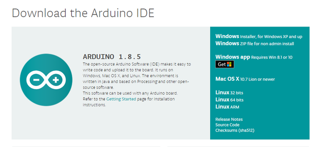
Arduino IDE is the open-source software to write sketch code and upload it to the Arduino microcontroller board. Arduino IDE runs on Windows, Mac OS X, and Linux. The environment is written in Java and based on Processing and other open-source software. We can choose between the Installer Windows (.exe) and the Zip packages. Arduino suggests us to use the first one that installs directly everything you need to use the Arduino Software (IDE), including the drivers. With the Zip package, you need to install the drivers manually. The Zip file is also useful if you want to create a portable installation.
Download the Arduino Desktop IDE: https://www.arduino.cc/en/Main/Software
When the download is finished, un-zip it and open up the Arduino folder to confirm that click yes, there are some files and sub-folders inside. The file structure is important so don’t be moving any files around unless you really know what you’re doing.
We can power and program the colored OLED display using SSD1331 library by adafruit Download the.ZIP library here:
SSD1331 Library: https://github.com/adafruit/Adafruit-SSD1331-OLED-Driver-Library-for-Arduino
INCLUDE Adafruit-SSD1331 Library to IDE
Arduino suggests us to use the 2 procedures on how to add libraries to the IDE (1) Add zip file library. this process needs a couple of clicks or we can call it the manual mode. once we have downloaded the zip library. Launch the Arduino IDE then navigate to "SKETCH" > "INCLUDE LIBRARY"> add ZIP library then locate the downloaded library in your DOWNLOADS Folder
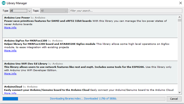
(2) The search install process. This process is easy than manually adding the library as all we need is to search for the library and install it inside the IDE. Click on "TOOL" > "MANAGE LIBRARIES". or simply. Ctrl+Shift+I.
Arduino uses libraries to program electronic devices easily. The predefined libraries are written in C and C++ language, One can even write his software in C\C++ and use them on Wiring boards. While sketching hardware we need to call the predefined functions and rest will be handled by the Wiring software.
DEFINE Colours Code
I am using a color OLED screen and so far I was using only bitmaps. It is not a standard HEX format(6 letters) but it has 4 letters.
This is color codes i got along whith library(Adafruit GFX):
#define BLACK 0x0000
#define BLUE 0x001F
#define RED 0xF800
#define GREEN 0x07E0
#define CYAN 0x07FF
#define MAGENTA 0xF81F
#define YELLOW 0xFFE0
#define WHITE 0xFFFF
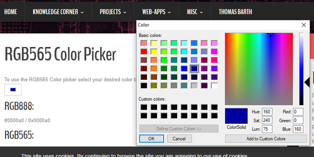
We can customize the color we want as the OLED can support 65k different kinds of color, We are able to use the color picker, The format is called RGB565. It is similar to RGB888, but only uses 16 bits (5+6+5) instead of 24 (8+8+8) and so has less fine control over the colors (less colors available overall). Here's a website to help calculate RGB565 values, but you should try to understand the format because it is not terribly difficult. HTTP://www.barth-dev.de/online/rgb565-color-picker/
INCLUDE/SET the variables, libraries, oled address .etc
#include <Adafruit_GFX.h>
#include <Adafruit_SSD1331.h>
#include <SPI.h>
Adafruit_SSD1331 display = Adafruit_SSD1331(cs, dc, rst);
The adafruit GFX for Arduino provides a common syntax and set of graphics functions for all of our LCD and OLED displays. We dont need to install it as its built-in arduino IDE software libraries. The Serial Peripheral Interface (SPI) is a synchronous serial data protocol used by microcontrollers for communicating with one or more electronic devices for quickly over short distances( OLED screen in this case)
INITIALIZE The SETUP Functions
void setup() {
display.begin();
display.fillScreen(RED);
delay(300);
display.fillScreen(GREEN);
delay(300);
display.fillScreen(BLUE);
delay(300);
display.fillScreen(BLACK);
delay(1000);
display.setCursor(20,5);
display.setTextColor(MAGENTA);
display.setTextSize(2);
display.print("Hello");
display.setCursor(8,25);
display.setTextColor(BLUE);
display.setTextSize(2);
display.print("Utopian");
display.fillRect(10,40, 80, 20, RED);
display.setCursor(20,47);
display.setTextColor(WHITE);
display.setTextSize(1);
display.print("lapilipinas");
display.drawRect(0,0,96,64,WHITE);
delay(1000);
}
The first line of the sketch provides information about the function, "setup". The text before and after the name specify its return type and parameters. the { and } is called the body of setup the function.
The setup() is called once, or the first booth when the sketch starts. on booth I decided to fill the LCD in 4 colors RED, GREEN, BLUE and BLACK before the welcome TEXT " HELLO" which text color is set to MAGENTA. The delay() causes the Arduino to wait for the specified number of milliseconds before continuing on to the next line. There are 1000 milliseconds in 1 second
INITIALIZE The LOOP() Functions
void loop() //this runs over and over again
{
display.fillRect(10,40, 80, 20, BLACK);
delay(1000);
display.fillRect(10,40, 80, 20, RED);
display.setCursor(20,47);
display.setTextColor(WHITE);
display.setTextSize(1);
display.print("Open-Source");
delay(1000);
display.fillRect(10,40, 80, 20, BLACK);
delay(1000);
display.fillRect(10,40, 80, 20, BLUE);
display.setCursor(20,47);
display.setTextColor(WHITE);
display.setTextSize(1);
display.print("Arduino");
delay(1000);
display.fillRect(10,40, 80, 20, BLACK);
delay(1000);
display.fillRect(10,40, 80, 20, GREEN);
display.setCursor(20,47);
display.setTextColor(WHITE);
display.setTextSize(1);
display.print("Project");
delay(1000);
}
The loop() function is run over and over until you un-plug it and it is the heart of most sketches. You need to include both functions in your sketch, the setup and loop even if you don't need them for anything. The Graphics: fillRect(int x, int y, int width, int height) in this case "fillRect(10,40, 80, 20,colorcode)" in 128x64 Oled.
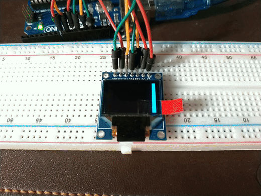
The Connection of OLED to Arduino R3 Board

The display module can display 65 thousand colors it uses the SPI interface so we have to connect 7 pins in order to make it work. So we need more wires in order to connect it with Arduino. GND or the common ground pin goes to Arduino GND. Vcc pin goes to either 3.3V or 5V ( preferred 3.3v) output of the Arduino. The next pin of the display is named SCL which is a mistake. It is actually the CLK pin of the SPI interface. So CLK pin goes to digital pin 13 on the Arduino. The next pin SDA but it is actually MOSI pin of the SPI interface. So the 4th pin of the display goes to digital pin 11. The next pin is RES or the reset which goes to digital pin 9. The 6th pin is DC which goes to digital pin 8. The last pin is CS which goes to digital pin 10. That’s it, we have connected the display to the hardware SPI pins of the Arduino Uno r3 board.
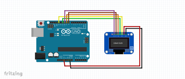
OLED PIN Arduino PIN
GND GND
VCC 3.3V
SCL: 13
SDA: 11
RES:9
DC: 8
CS :10
Connect the Arduino microcontroller to your computer via USB cable(TYPE glasses emoticon.
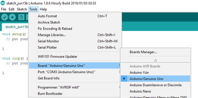
your computer will automatically scan the device driver, to verify the board of the Arduino, on the IDE click >. TOOLS then verify the board type and PORT where the USB is connected.
Copy the source code to Arduino IDE sketch bar. Click the UPLOAD icon on the upper right side toggle, it will automatically compile the sketch to check if there's an error with the code before uploading to the Arduino board, all done.
Conclusion
I have created this kind of Arduino activity about the OLED display for steemit and steelmakers on past months it is the Arduino blog no. 10, but not illustrative as this post as I only posted the code and the result of the work. and today I remake it as my contribution to utopian. re-scaling the full rectangular code is not easy work especially for beginners as you need to test upload the code again and again. all in all I spent my time in a very fun productive activity.
Useful links and references
Arduino Main Website
: https://www.arduino.cc
SSD1331 library by adafruit for colorOLED
: https://github.com/adafruit/Adafruit-SSD1331-OLED-Driver-Library-for-Arduino
Diagram created using Fritzing
: http://fritzing.org/download/
Screenshots edited using MS paint and blog created using BUSY
: https://busy.org/
Animated Gif created using Gfycat
: https://gfycat.com