There is a binary number system, using which devices such as computers, calculators, and other types of electronic devices are being used. Given this, perhaps we could not even imagine that because all the processing performed in the computer is only in the form of 1 and 0 and we get the results only by processing all the operations. However, I am not too much about binary operations now. I would like to announce that in this post I will only verify and show you the basic gates logic gate like (AND, OR, XOR, NOT, NAND, NOR, and XNOR).
And with the help of these gates, how can we make a circuit by increasing its complexity, and how many types of operations can be performed?
Many circuits and many motherboards are made using these Basic gates.

Types of Logic Gates
- Basic Gates
- Universal Gates
- Special Gates
Basic Gates (AND Gate, OR Gate, NOT Gate)
1. AND GATE👇
First of all, I will talk about the AND gate, this gate has two inputs and one output, as I already told you that in any gate we could give only two types of inputs 0 or 1. This gate is such that until both its inputs become 1, it does not provide output 1 i.e. if we give 0 as input to either of the two inputs then we will never get 1 output.
img src
TRUTH TABLE OF AND GATE
| INPUT | INPUT | OUTPUT |
|---|
| A | B | C(OUT) |
| 0 | 0 | 0 |
| 0 | 1 | 0 |
| 1 | 0 | 0 |
| 1 | 1 | 1 |
2. OR GATE👇
Now moving towards our next gate OR gate or gate is almost similar to this gate because it also has two inputs and one output we give input in both and we get the result on output but its truth table is different Or are the truth tables of all gates different from each other and in its truth table also we can get 1 in the output when at least one value in the input is 1.
img src
TRUTH TABLE OF OR GATE
| INPUT | INPUT | OUTPUT |
|---|
| A | B | C(OUT) |
| 0 | 0 | 0 |
| 0 | 1 | 1 |
| 1 | 0 | 1 |
| 1 | 1 | 1 |
3. NOT GATE👇
Now the next gate is NOT a gate that has only one input and only one output, in reverse any signal, this gate is always used. That is, whatever we give in the input, we get its opposite in the output. Only two values can be given in its truth table. By giving zero, we get 1 and by giving 1, we get 0.
img src
TRUTH TABLE OF NOT GATE
| INPUT | OUTPUT |
|---|
| A | C(OUT) |
| 1 | 0 |
| 0 | 1 |
Universal Gates (NAND Gate, NOR Gate)
1. NAND GATE👇
Our next basic gate is going to be NAND, in actual this gate can also be made by combining two gates, both the gates are AND and NOT, when we put the NOT gate in the output of AND gate, then we get the truth table of NAND i.e. If we do the opposite of the truth table of AND gate, then we will get the truth table of NAND gate.
img src
TRUTH TABLE OF NAND GATE
| INPUT | INPUT | OUTPUT |
|---|
| A | B | C(OUT) |
| 0 | 0 | 1 |
| 0 | 1 | 1 |
| 1 | 0 | 1 |
| 1 | 1 | 0 |
2. NOR GATE👇
And just like the NAND gate, our next gate is NOR gate. We can also make this gate by a combination of NOT and OR. If we put the NOT gate on the output of the OR gate, then the truth table of this combination is like the truth table of the NOR gate. It happens or we can also say that even if all the outputs of OR are made opposite to it, we still get the same result.
src
TRUTH TABLE OF NOR GATE
| INPUT | INPUT | OUTPUT |
|---|
| A | B | C(OUT) |
| 0 | 0 | 1 |
| 0 | 1 | 0 |
| 1 | 0 | 0 |
| 1 | 1 | 0 |
Special Gates (XOR Gate, XNOR Gate)
1. XOR GATE👇
XOR gate is also a normal gate like these gates, which has 2 inputs and one output when we give the same input, it returns 0 and when we give different inputs, it returns 1.
img src
TRUTH TABLE OF XOR GATE
| INPUT | INPUT | OUTPUT |
|---|
| A | B | C(OUT) |
| 0 | 0 | 0 |
| 0 | 1 | 1 |
| 1 | 0 | 1 |
| 1 | 1 | 0 |
2. XNOR GATE👇
XNOR gate also has 2 inputs and one output but when we give the same input then the output is 1 but when we differentiate both inputs the output is 0 then this gate is XNOR.
src
TRUTH TABLE OF XNOR GATE
| INPUT | INPUT | OUTPUT |
|---|
| A | B | C(OUT) |
| 0 | 0 | 1 |
| 0 | 1 | 0 |
| 1 | 0 | 0 |
| 1 | 1 | 1 |
Basic ICS and their gates
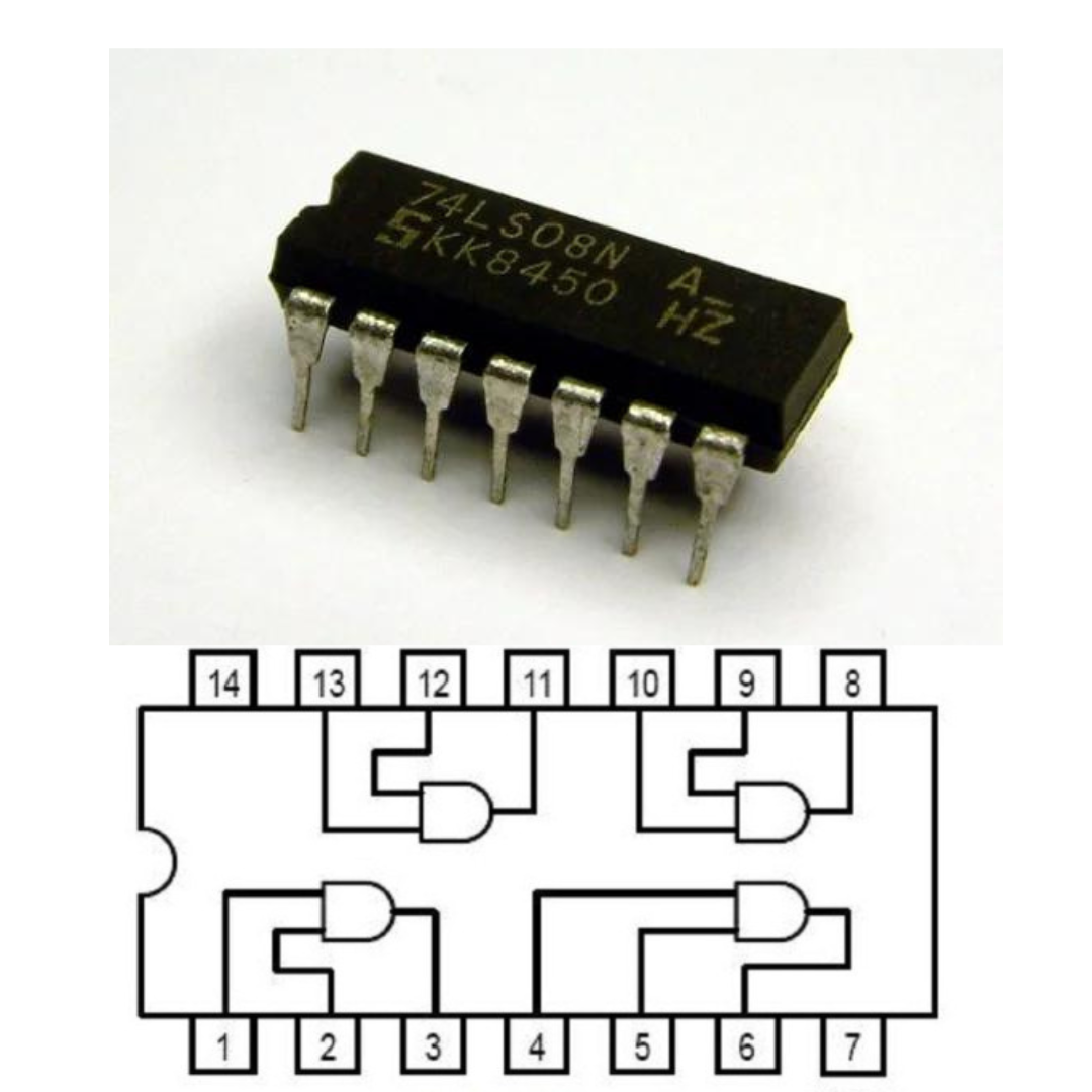
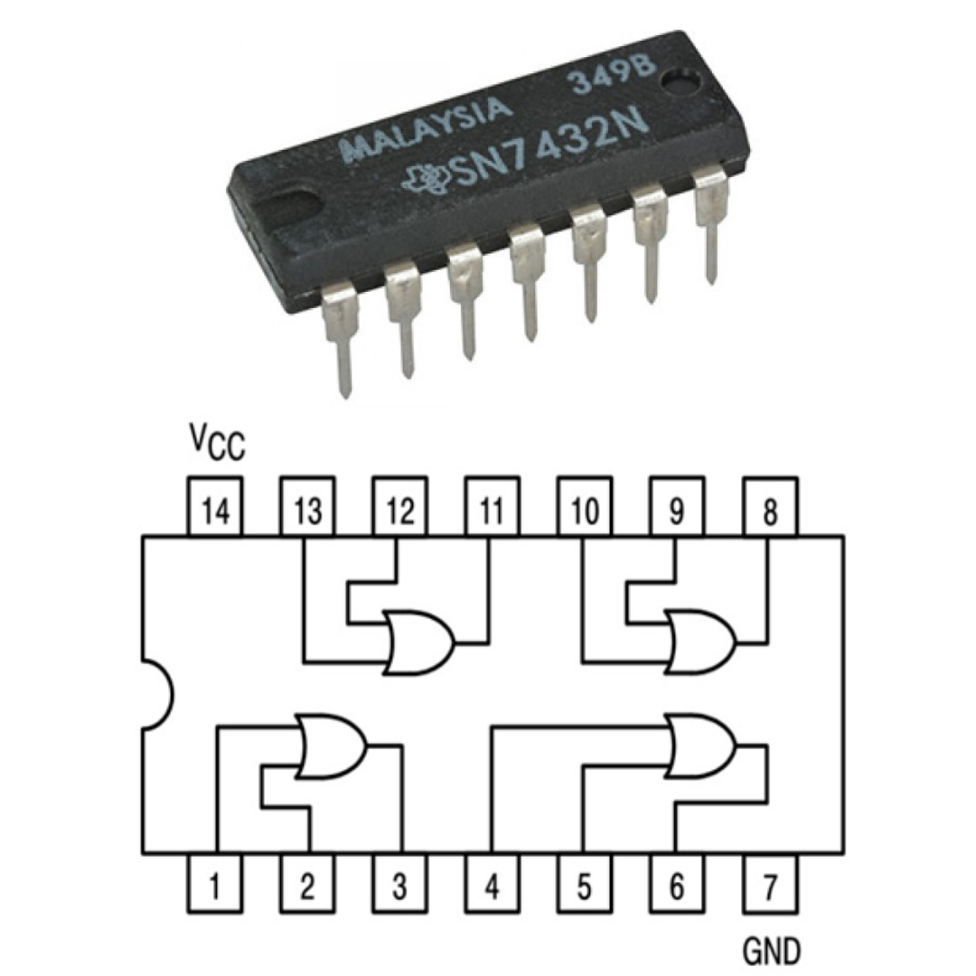
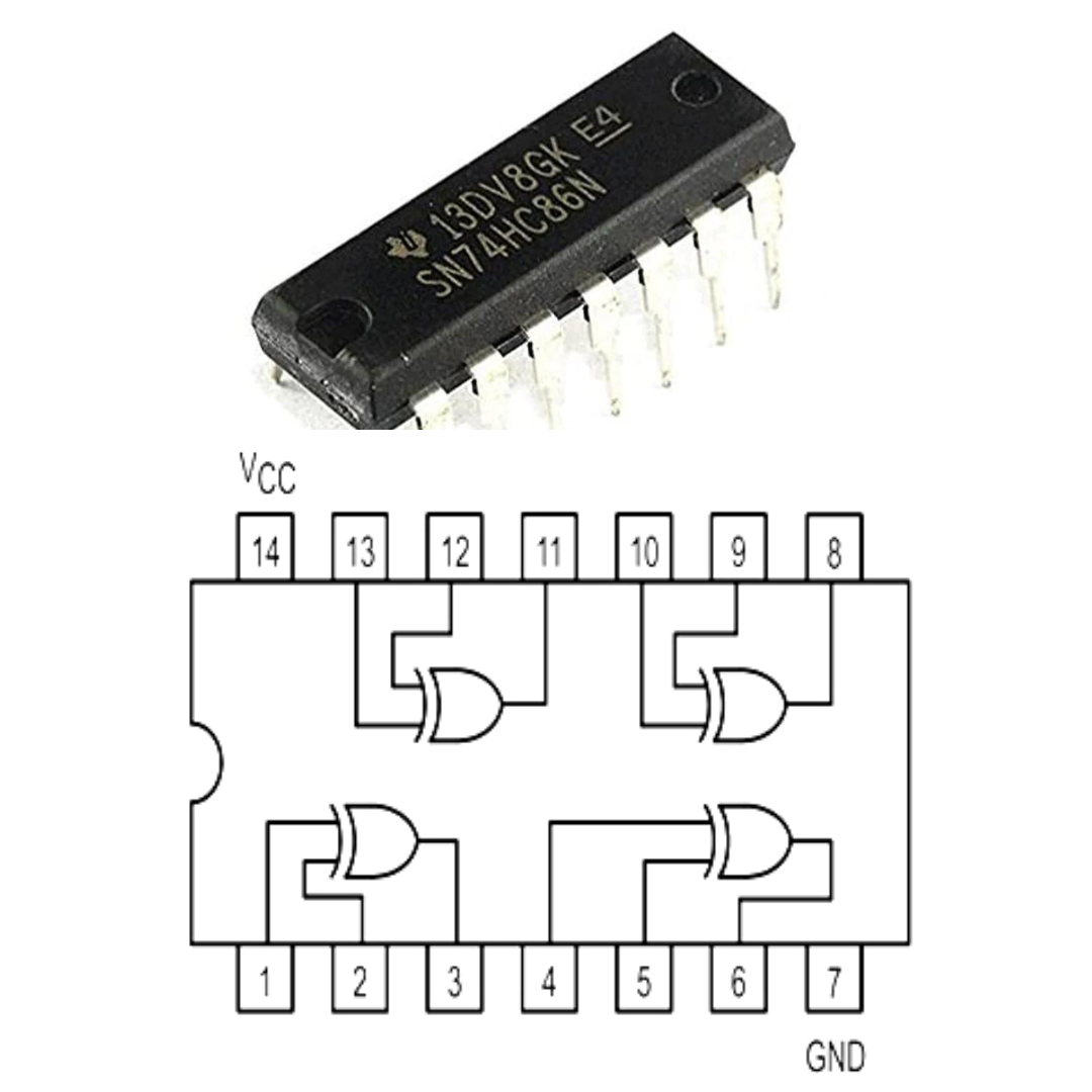
So far we have read so much about the gates, I am going to show myself where it is used all these gates are used in ICs inside it and they have 14 pins, in which we give voltage to PIN 14. and PIN 7 is grounded by doing this first we provide voltage in these ICs and then we can use IC now I will tell you in a sequence how we can use these IC' different types of gates to verify.
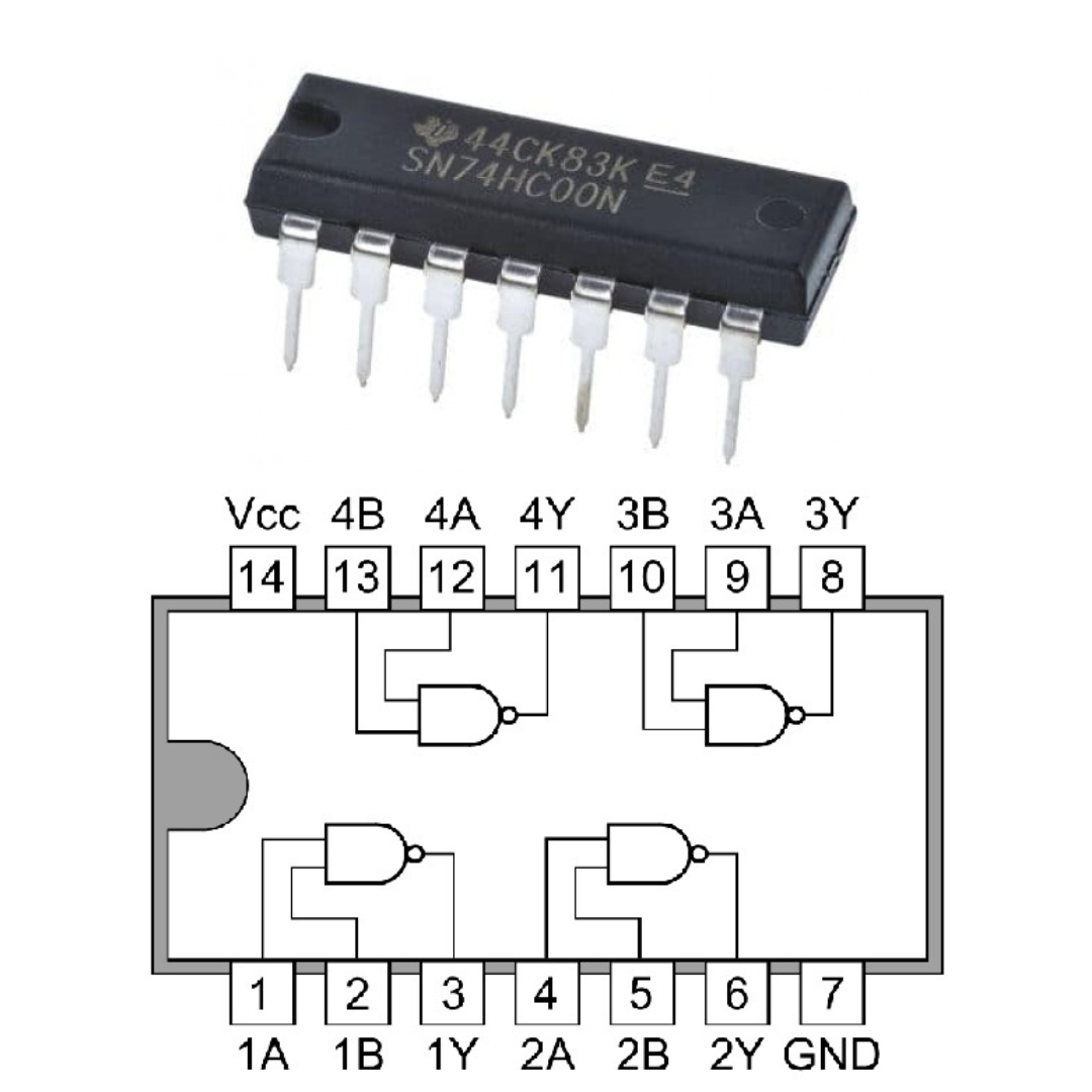
First of all, I will talk about IC number 7400. In this IC, a NAND gate is used, in which 4 NAND gates are used, which are engaged in order, as shown in the image, output on PIN 13, 10, 1, and 4. and the PINs 12, 11, 9, 8, 2, 3, 5, 6 belong to the input.
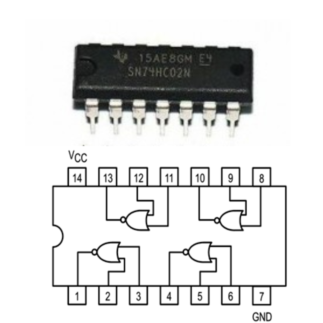
Now moving towards our next IC number 7402, in this IC also 4 NOR gates are used, which are connected in a sequence as seen in the image, whose PIN 14 gives voltage and PIN 7 gives ground. And talking about its input and output, PIN 11, 8, 3, and 6 are the output pins while the pins of the input are 13, 12, 10, 9, 1, 2, 4, and 5.
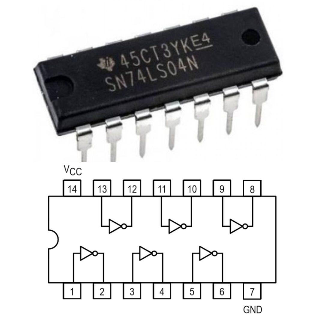
Our next IC number is 7404. In this IC there are 6 NOT gates which are in order. you can see in the image it has input and output on alternate it also very clearly you can see in its image we give voltage in its PIN 14 and ground on its PIN 7.
Our next IC number is 7432, it also has 4 OR gates and it also gives voltage on PIN 14 and ground on PIN 7. All four gates are connected in order or you can see it clearly in the image. You can take output on PIN 11, PIN 8, PIN 3, and PIN 6, and you can give input in all the remaining pins.
Now our next IC is IC number 7486, in this 4 XOR gates are used and like other gates, we give voltage on PIN 14 and ground on PIN 7, all gates are connected in a sequence in which We can take output on PIN 11, PIN 8, PIN 3 and PIN 6, apart from this, we can give input on all other pins, but all these inputs can be taken in one order only by giving input, as you can see in the picture.
Using components and kits
Now we will talk about the component used in it so that we will be able to verify all the gate truth tables.
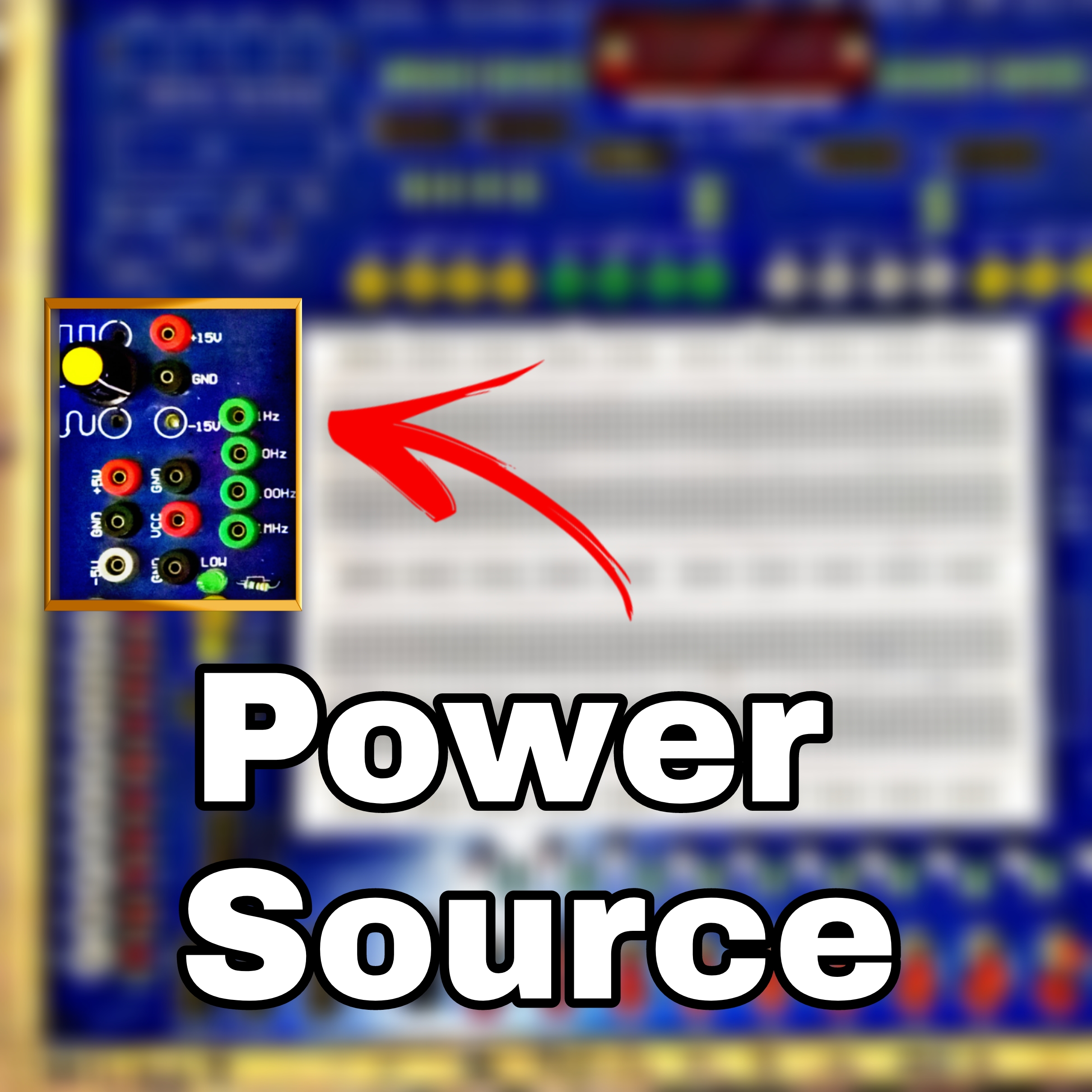
1. Analog Digital Trainer Kit
And for this we use Analog and Digital Trainer Kit, this complete kit helps us to make and verify any circuit, it has mostly 4 parts which we use most, and apart from this, different circuits It is used in making and verifying its truth table, it is mostly divided into 4 parts and helps make or verify any digital and analog circuit.

The first part of this helps us to provide voltage, in which we can give from 0 volts to a maximum of 15 volts and also give negative voltage if needed but we use mostly 5 volts in normal gates because 5 volts 1 is used as input.
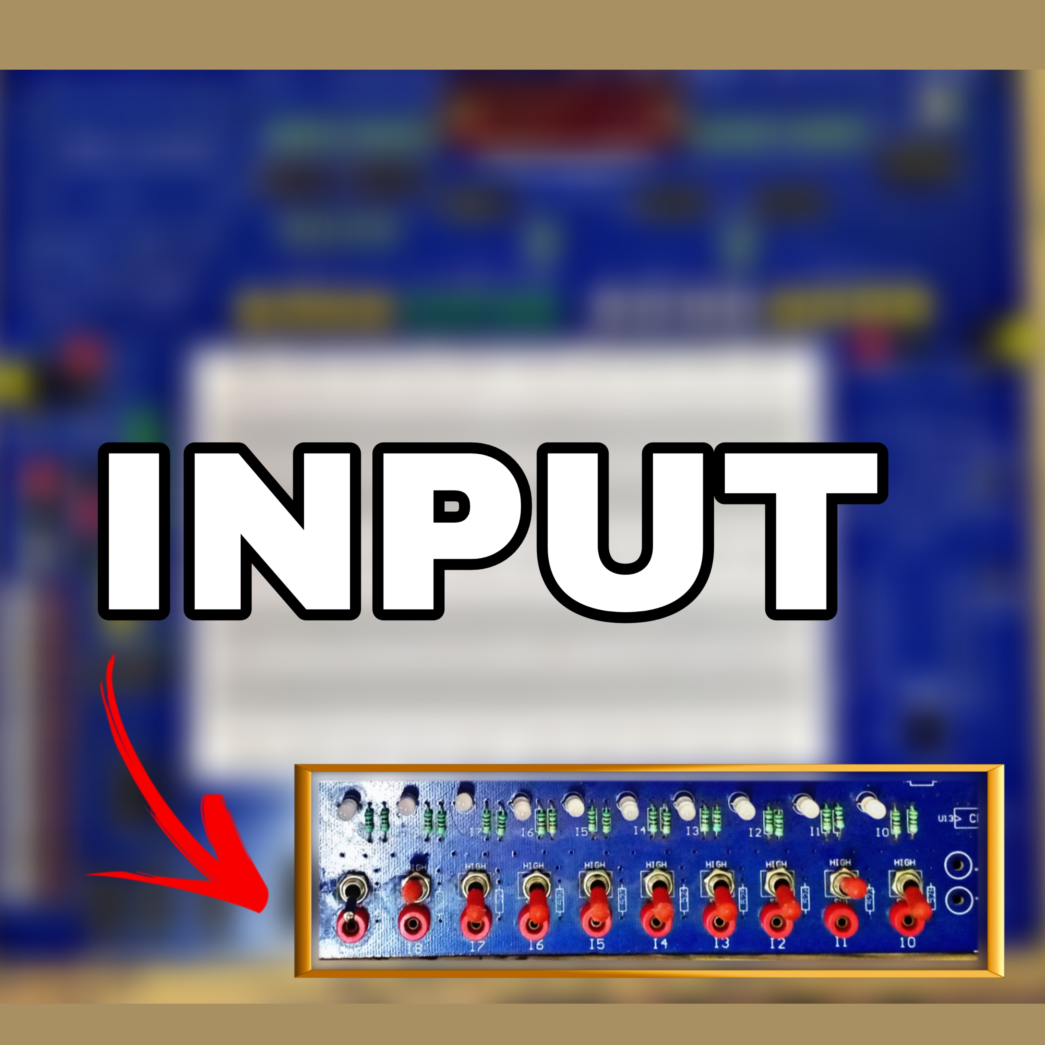
And its second part is input which is like a switch by turning on which we can give input 0 or 1 by turning it on or off the input, in most of the cases we consider 5 volts as input 1 but where we have to change has to be done, there the input to be given from the switch itself because by which we can verify the result by changing and if in any case, we have to keep the input on then we continuously give 5 volts if in any case, we have to input If we want to keep it always zero then we can keep it open-circuit also.
And the third part of this kit is the output, on which we can see our results. There are small LED bulbs on its side, when the LED bulb gets burnt, we consider it as output 1, but when this LED bulb remains off, we consider it as output 0.
And its main part is the breadboards on which we make our entire circuit, the breadboard's internal lines which are at the top and bottom are horizontally connected while all the lines in the middle are vertically connected and all have one There is a point hole through which we can prepare our circuit and perform any digital or analog circuit.
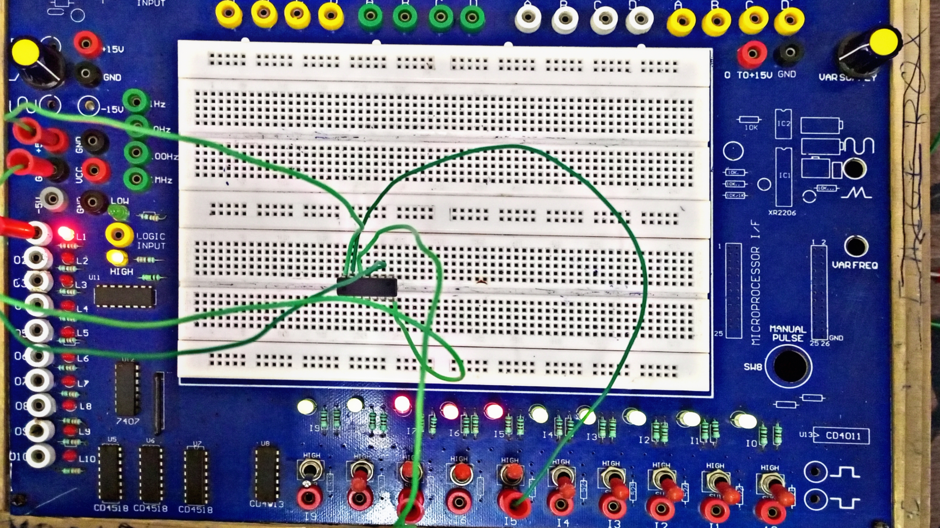
Final Circuit Making
To make the final circuit, we first give power to the ICs and then give the input, see the final result in the output and make a table of input and output, match it with the original, and verify it. What is the gate in any IC? and how is his truth table
🙏🙏Thanking You..........🙏🙏
Posted with STEMGeeks





Thanks for your contribution to the STEMsocial community. Feel free to join us on discord to get to know the rest of us!
Please consider delegating to the @stemsocial account (85% of the curation rewards are returned).
You may also include @stemsocial as a beneficiary of the rewards of this post to get a stronger support.
Congratulations @waverunner! You have completed the following achievement on the Hive blockchain And have been rewarded with New badge(s)
Your next target is to reach 4500 upvotes.
You can view your badges on your board and compare yourself to others in the Ranking
If you no longer want to receive notifications, reply to this comment with the word
STOPCheck out our last posts:
Support the HiveBuzz project. Vote for our proposal!
Wow, this is really detailed.
!discovery 43
Thank you ❤️
This post was shared and voted inside the discord by the curators team of discovery-it
Join our community! hive-193212
Discovery-it is also a Witness, vote for us here
Delegate to us for passive income. Check our 80% fee-back Program