[ENG|ESP] LED Dot Matrix and MAX7219 Driver, a Power Couple | Matriz de Puntos de Leds y el Driver MAX7219, una Pareja Poderosa.
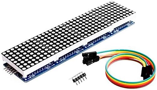
A while ago I shared some pictures of an interesting project in a short post. It was about a pair of eyes made out of LEDs, to be more specific they were recreated through a pair of dot matrix modules based on the MAX7219 driver. Basically this driver is a circuit that allows to drive a considerable amount of LEDs in a multiplexed way. What does that mean? I will explain it in a moment.
Hace un tiempo compartí en un breve post algunas fotos de un interesante proyecto. Se trataba de un par de ojos hechos a base de diodos leds, para ser más específicos fueron recreados a través de un par de módulos de matriz de puntos basados en el driver MAX7219. Básicamente este driver es un circuito que permite manejar una cantidad considerable de leds de forma multiplexada. ¿Qué quiere decir eso? En seguida se los explico.
To turn an individual LED on or off, it needs to be connected or disconnected from a power source. If it's an automated system that involves programming then the controller device in charge of the process will be responsible for that through one of its digital outputs. Each digital output is simply a pin or electrical terminal through which the voltage that will make the LED turn on or off will be applied. Under this philosophy, for each independent LED that you want to include in the system, it will be necessary to use a digital output of the controller. This doesn't represent a great inconvenience if they are few but the digital outputs of a controller device are limited and if there are many LEDs we can be short of hardware resources.
Para encender o apagar un led individual se necesita que éste sea conectado o desconectado de una fuente de energía. Si se trata de un sistema automatizado que involucre programación entonces el dispositivo controlador a cargo del proceso será el responsable de eso a través de una de sus salidas digitales. Cada salida digital es simplemente un pin o terminal eléctrico por el cual se reflejará el voltaje que hará que el led se encienda o se apague. Bajo esta filosofía, por cada led independiente que se desee incluir en el sistema, será necesario usar una salida digital del controlador. Esto no representa gran inconveniente si son pocos pero las salidas digitales de un dispositivo controlador son limitadas y si se trata de muchos leds nos podemos quedar cortos de recursos de hardware.

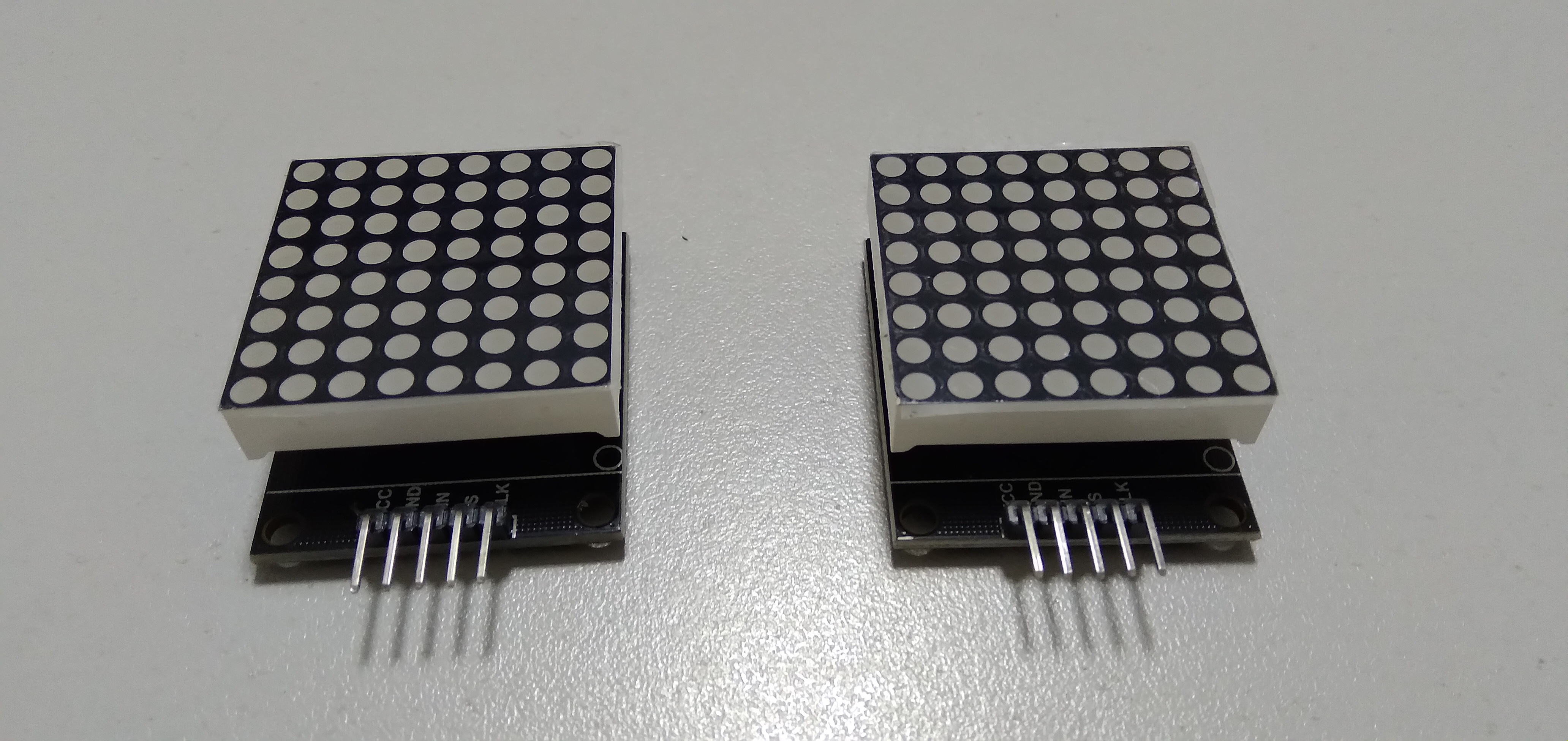
The LED matrix in question has 8 rows and 8 columns for a total of 64 LEDs, so if we were dealing with 64 individually controlled LEDs we would need 64 digital outputs from the controller to achieve this goal. Even if we had a device with that number of outputs this situation wouldn't be recommended because the automated system to be implemented probably has other components that also require a connection to the controller terminals. Instead, by being organized in a matrix and its connections (by rows and columns), the LEDs will work in a multiplexed operation through a shift system with an update rate that deceives the human eye, allowing it to perceive that all LEDs can light simultaneously.
La matriz de leds en cuestión tiene 8 filas y 8 columnas para un total de 64 leds, por lo tanto si se tratara de 64 leds controlados individualmente se necesitaría apartar 64 salidas digitales del controlador para lograr este objetivo. Aun cuando tuviéramos un dispositivo con esa cantidad de salidas no sería recomendable esta situación porque probablemente el sistema automatizado a implementar tenga otros componentes que también requieran una conexión con los terminales del controlador. En cambio, al estar organizados en una matriz, las conexiones de la misma (por filas y columnas) garantizan que los leds funcionarán de manera multiplexada a través de un sistema de turnos con una velocidad de actualización que engaña a la vista humana permitiéndole percibir que todos los leds pueden encender simultáneamente.
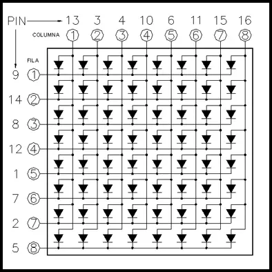
With the previously mentioned structure we would only need 16 digital pins of the controller (8 for the columns and 8 for the rows). However, depending on the controller to be used it could still be expensive to allocate 16 controller pins for this purpose. In many cases more than one matrix of this type are used connected in series, so the number of pins needed to control them ( already reduced thanks to the matrix array) will increase. This is where the MAX7219 driver comes in handy.
Con la estructura mencionada sólo necesitaríamos 16 pines digitales del controlador (8 para las columnas y 8 para las filas). Sin embargo, dependiendo del controlador a usar aún podría ser costoso destinar 16 pines del mismo para este fin. En muchos casos son usadas más de una matriz de este tipo conectadas en serie, por lo cual el número de pines necesarios para controlarlas (previamente reducido gracias al arreglo matricial) se incrementará. Es aquí donde el driver MAX7219 es de gran utilidad.
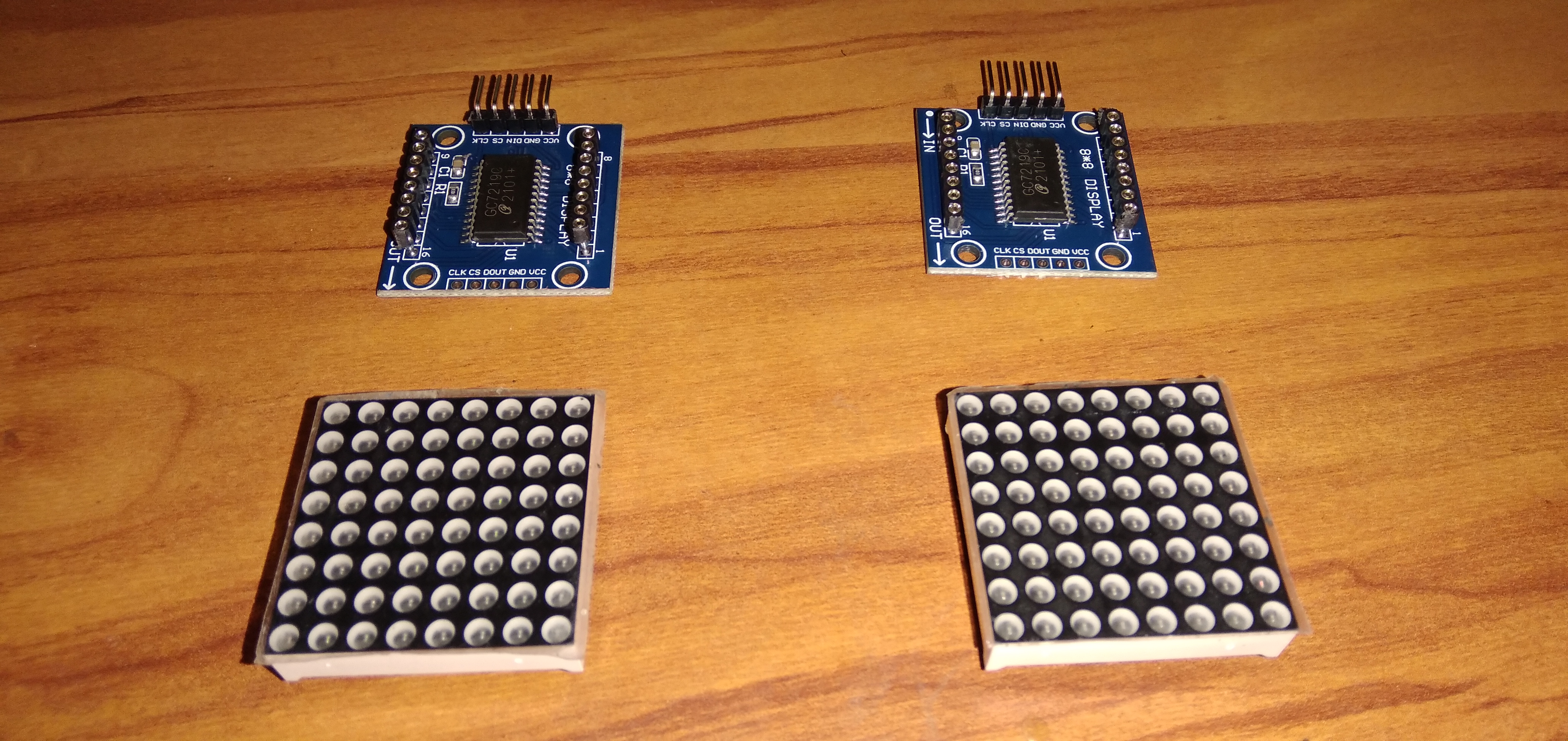
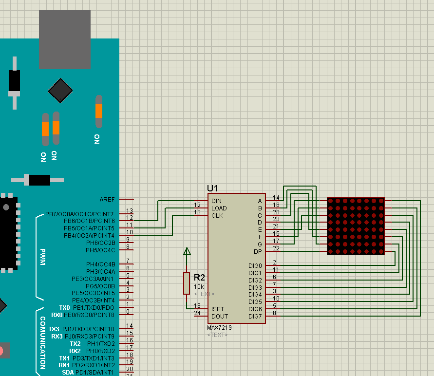
This chip is connected to the dot matrix through its rows and columns terminals but only needs 5 pins to communicate with the rest of the system, of which 2 are for the power supply and can be connected directly to an external power source, while the remaining three receive the signals coming from the controller: DIN or DATA IN, through which the controller passes all the information to be displayed by the LEDs; CLK or CLOCK, which is the clock signal for the multiplexed shifts and the synchronization of all the connected devices; and finally the LOAD or CS pin. We can observe in the following image that we will only need 3 digital pins of the controller in contrast to the 64 that we would need if there were no multiplexing and matrix-arranged leds.
Este integrado se conecta a la matriz de puntos a través de sus filas y columnas pero sólo necesita 5 pines para comunicarse con el resto del sistema, de los cuales 2 son de alimentación y pueden provenir directamente de una fuente externa de energía, y los tres restantes para las señales provenientes del controlador: DIN o DATA IN, por donde el controlador pasa toda la información a ser mostrada por los leds; CLK o CLOCK, que es la señal de reloj para los turnos del multiplexado y la sincronización de los distintos dispositivos conectados; y finalmente el pin LOAD o CS. Podemos observar en la siguiente imagen que sólo necesitaremos 3 pines digitales del controlador en contraste con los 64 que necesitaríamos si no existiese el multiplexado y los leds organizados en forma de matriz.

0
0
0.000
Congratulations @warrior.tech! You have completed the following achievement on the Hive blockchain And have been rewarded with New badge(s)
Your next target is to reach 200 upvotes.
You can view your badges on your board and compare yourself to others in the Ranking
If you no longer want to receive notifications, reply to this comment with the word
STOPCheck out our last posts: