13-06-2024 - Energy systems - Pump-system coupling[EN]-[IT]

~~~ La versione in italiano inizia subito dopo la versione in inglese ~~~
ENGLISH
13-06-2024 - Energy systems - Pump-system coupling[EN]-[IT]
Real and isentropic work
Pump-system coupling
The meaning of prevalence
In fluid dynamics, head can be seen as the energy per unit of weight that a fluid has in a pumping system. We can say that the head expresses the increase in energy that a fluid receives when it passes through a pump. This energy is expressed as if it were a height and is called prevalence height.
In other words we can also write that the head is a measure of the energy that a pump must provide to a fluid to overcome the inertia, friction and height differences of the hydraulic system under consideration.
The prevalence is made up of 3 characteristic prevalences listed below:
Static head Hs
Hd dynamic prevalence
Prevalence of Hf losses
The general prevalence formula is as follows:

Where:
H = total head
Hs = static head
Hd = dynamic head
Hf = head of losses
Concentrated losses
Fluid dynamic losses can be of two types:
-concentrated losses
-distributed losses
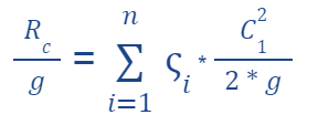
Concentrated losses are expressed with the following formula:

Concentrated losses are proportional to the square of the velocity. This also applies to distributed losses.
Concentrated losses have localized resistance coefficients, below is the formula relating to the issue:

These localized resistance coefficients are tabulated for the various elements of the systems.
Distributed fluid dynamic losses
The distributed fluid dynamic losses are expressed as follows:

These types of losses are:
-proportional to the friction factor and the length of the duct
-inversely proportional to the diameter of the duct
The relationship that regulates the distributed losses is the following:

NOTE:
-For laminar flows the friction factor is related to the Reynolds number
-For turbulent flows the friction factor is independent of the Reynolds number and dependent on the roughness of the pipes.
Conclusions
We can say that the operating point of a pump is strongly dependent on the hydraulic circuit in which it is inserted.
Request
Have you ever had to calculate the losses of a fluid dynamic system?

ITALIAN
13-06-2024 - Sistemi energetici - Accoppiamento pompa-impianto[EN]-[IT]
Lavoro reale e isoentropico
Accoppiamento pompa-impianto
Il significato di prevalenza
In fluidodinamica, la prevalenza può essere vista come l’energia per unità di peso che un fluido possiede in un sistema di pompaggio. Possiamo dire che la prevalenza esprime l’aumento di energia che un fluido riceve quando passa attraverso una pompa. Questa energia si esprime come se fosse un’altezza e viene chiamata altezza di prevalenza.
In altre parole possiamo scrivere anche che la prevalenza è una misura dell'energia che una pompa deve fornire a un fluido per superare l'inerzia, l'attrito e le differenze di altezza del sistema idraulico preso in esame.
La prevalenza è composta da 3 prevalenze caratteristiche qui di seguito elencate:
Prevalenza statica Hs
Prevalenza dinamica Hd
Prevalenza delle perdite Hf
La formula generale della prevalenza è la seguente:

dove:
H = prevalenza totale
Hs = prevalenza statica
Hd = prevalenza dinamica
Hf = prevalenza delle perdite
Perdite concentrate
Le perdite fluidodinamiche possono essere di due tipi:
-perdite concentrate
-perdite distribuite
Le perdite concentrate si esprimono con la seguente formula:

Le perdite concentrate risultano proporzionali al quadrato della velocità. Questo è valido anche per le perdite distribuite.
Le perdite concentrate hanno dei coefficienti di resistenza localizzata, qui di seguito la formula inerente alla questione:

Questi coefficienti di resistenza localizzata sono tabulati per i vari elementi degli impianti.
Perdite fluidodinamiche distribuite
Le perdite fluidodinamiche distribuite si esprimono come segue:

Questa tipologia di perdite sono:
-proporzionali al fattore di attrito e alla lunghezza del condotto
-inversamente proporzionali al diametro del condotto
La relazione che regola le perdite distribuite è la seguente:

NOTA:
-Per flussi laminari il fattore di attrito è legato al numero di Reynolds
-Per flussi turbolenti il fattore di attrito risulta indipendente dal numero di Reynolds e dipendente dalla rugosità delle tubazioni.
Conclusioni
Possiamo dire che il punto di funzionamento di una pompa è fortemente dipendente dal circuito idraulico in cui è inserita.
Domanda
Avete mai dovuto calcolare delle perdite di un sistema fluidodinamico?
THE END
This is my first time getting to know a fluid dynamic system
I’ve never calculated one before though but thanks for the class
Ooh wow
This course is interesting but has a very crazy formula
Thanks for the interesting class though
I think with your post today, I have really been able to know more about the fluid dynamic system and this is great to see
Non ho eseguito questi calcoli