11-06-2024 - Energy systems - characteristic curves [EN]-[IT]

~~~ La versione in italiano inizia subito dopo la versione in inglese ~~~
ENGLISH
11-06-2024 - Energy systems - characteristic curves [EN]-[IT]
Ideal characteristic curves
Ideal curve of a centrifugal pump
The ideal curve of a centrifugal pump is obtained by analyzing the flow rate Q and the total head H. The graph is shown below.
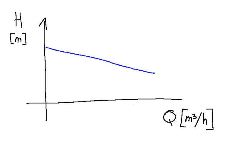
The more the flow rate increases, the lower the head is.
NOTE: Head is a measure of the energy per unit weight of a fluid that can be converted to height. It is an important concept for analyzing the behavior of fluids in hydraulic systems. The head data is fundamental when designing a hydraulic system and it is necessary to size pipes, pumps or turbines.
Impeller blades
If we take into consideration a centrifugal pump we can say that depending on how the impeller blades are facing, the head changes.
Listed below are the three ways in which the blades can be turned and their effects.
-If the blades are facing forward the head increases with the flow rate
-If the blades are radial the head is constant
-If the blades are facing backwards the head decreases with the flow rate.
It must be taken into consideration that when the flow rate increases the absolute speed also increases and consequently the fluid dynamic losses also increase.
This is why back-swept or radial blades are often chosen
Hydraulic leaks
The types of hydraulic losses suffered by the fluid when passing through a centrifugal pump can be the following.
-Friction losses (or mechanical friction losses)
-Turbulence losses (or internal turbulence losses)
-Volumetric losses (or leak losses)
Hydraulic shock losses (or losses due to abrupt changes in direction and speed)
-Losses due to bottlenecks (or localized losses)
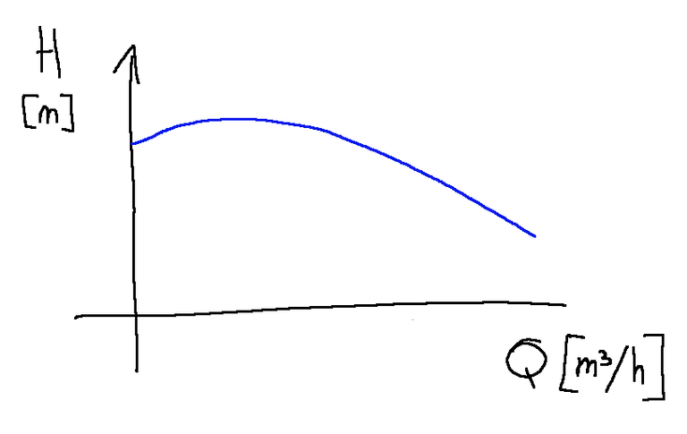
Real curve of a centrifugal pump
The real curve of a centrifugal pump is obtained by analyzing the flow rate Q and the total head H. The graph is shown below.
The total hydraulic or fluid dynamic losses will influence the ideal curve and we will obtain the graph of the real curve. (see image below)
Conclusions
In a centrifugal pump the ideal and real curves differ from the fact that in the real ones the hydraulic losses of the operating machine, i.e. of the pump itself, are also calculated.
Request
In the past I happened to design systems with hydraulic pumps and to view their operating curves.
Have you ever taken a look at the operating curves of a hydraulic pump?
![]()
ITALIAN
11-06-2024 - Sistemi energetici - curve caratteristiche [EN]-[IT]
Curve caratteristiche ideali
Curva ideale di una pompa centrifuga
La curva ideale di una pompa centrifuga si ottiene analizzando la portata Q e la prevalenza totale H. Il grafico è riportato qui sotto.
Più aumenta la portata e più si abbassa la prevalenza.
NOTA: la prevalenza è una misura dell'energia per unità di peso di un fluido che può essere convertita in altezza. È un concetto importante per l'analisi del comportamento dei fluidi nei sistemi idraulici. Il dato della prevalenza è fondamentale quando si progetta un sistema idraulico e bisogna dimensionare condotte, pompe o turbine.
Pale della girante
Se prendiamo in considerazione una pompa centrifuga possiamo dire che a seconda di come sono rivolte le pale della girante la prevalenza cambia.
Qui di seguito sono elencati i tre modi in cui possono essere rivolte le pale ed i relativi effetti.
-Se le pale sono rivolte in avanti la prevalenza aumenta con la portata
-Se le pale sono radiali la prevalenza è costante
-Se le pale sono rivolte all’indietro la prevalenza diminuisce con la portata.
Si deve tenere in considerazione che quando aumenta la portata aumenta anche la velocità assoluta e di conseguenza aumentano anche le perdite fluidodinamiche.
Questo è il motivo per cui spesso vengono scelte pale con inclinazione indietro o radiali
Perdite idrauliche
Le tipologie di perdite idrauliche subite dal fluido nell'attraversamento di una pompa centrifuga possono essere le seguenti.
-Perdite per attrito (o perdite per attrito meccanico)
-Perdite per turbolenza (o perdite per turbolenza interna)
-Perdite volumetriche (o perdite per fuga)
Perdite per shock idraulico (o perdite per cambiamenti bruschi di direzione e velocità)
-Perdite per strozzature (o perdite localizzate)
Curva reale di una pompa centrifuga
La curva reale di una pompa centrifuga si ottiene analizzando la portata Q e la prevalenza totale H. Il grafico è riportato qui sotto.
Le perdite idrauliche o fluidodinamiche totali influiranno sulla curva ideale ed otterremo il grafico della curva reale. (vedi immagine qui sotto riportata)
Conclusioni
In una pompa centrifuga le curve ideali e quelle reali differiscono dal fatto che in quelle reali sono calcolate anche le perdite idrauliche della macchina operatrice, cioè della pompa stessa.
Domanda
In passato mi è capitato di progettare sistemi con pompe idrauliche e di visionarne le curve di funzionamento.
Vi è mai capitato di dare un'occhiata alle curve di funzionamento di una pompa idraulica?
THE END
I've got to understand that differences between the real and the ideal curves in a centrifugal pump.
Is it possible to make use of this forumla for a pumping machine?
Are the impeller blades very much important in a pump?
!discovery 35
This post was shared and voted inside the discord by the curators team of discovery-it
Join our Community and follow our Curation Trail
Discovery-it is also a Witness, vote for us here
Delegate to us for passive income. Check our 80% fee-back Program
It is actually necessary to make use of this to solve other problems