08-07-2024 - Energy systems - Thermodynamic cycles[EN]-[IT]

~~~ La versione in italiano inizia subito dopo la versione in inglese ~~~
ENGLISH
ITALIAN
08-07-2024 - Energy systems - Thermodynamic cycles[EN]-[IT]
Thermodynamic cycles
T-s diagram
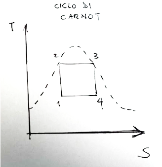
The T-s diagram of the Carnot cycle is shown below
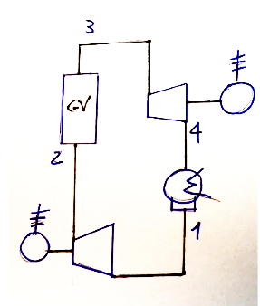
System diagram
Below is the system diagram which could constitute the ideal reference to the diagram proposed above.
The Carnot cycle
The Carnot cycle is an ideal model representing a heat engine. This heat machine is therefore an ideal heat machine that operates with the highest possible efficiency between two heat reserves (a tank with a higher temperature and a tank with a lower temperature)
The cycle is made up of 4 phases listed below:
-Isothermal expansion
-Adiabatic expansion
-Isothermal compression
-Adiabatic compression
If we look at the cycle on the T-s, temperature-entropy graph, we can identify the 4 phases as follows:
1-2 isentropic compression. Where there is an increase in pressure and the fluid exits in saturated liquid conditions.
2-3 steam generator. Where the fluid passes through an exchanger through which it receives heat from the thermal source and exits in saturated steam conditions,
3-4 isentropic expansion. Here the fluid produces work and is supplied to an external user,
4-1 capacitor. Phase in which the fluid passes through an exchanger through which it releases heat to the thermal sink.
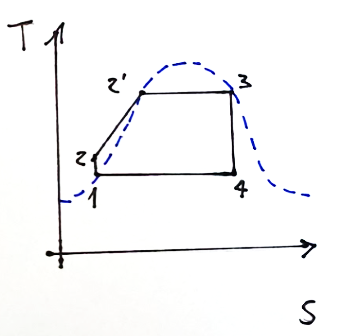
T-s diagram, Rankine
The T-s diagram of the Rankine cycle is shown below
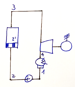
System diagram
Below is the diagram of the system which could constitute the ideal reference to the diagram proposed above which refers to the Rankine cycle.
The Rankine cycle
The Rankine cycle is similar to the Carnot cycle but there are some important differences.
The main differences between the Carnot cycle and the Rankine cycle are described below.
Below are the changes, so what is different compared to the Carnot cycle
-During condensation the exiting fluid reaches the condition of saturated liquid.
-The compression phase becomes a pumping phase of the saturated liquid. This means that at the exit of the pumping phase I will not have saturated liquid as in the previous case, but subcooled liquid.
-the steam generator, in addition to vaporizing the fluid, will also have to provide heat to bring the subcooled liquid to saturated conditions. This exchanger is also called economizer or pre-heater and carries out the 2-2' transformation
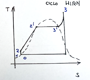
T-s diagram, Hirn
The T-s diagram of the Rankine cycle is shown below
System diagram
Below is the diagram of the system which could constitute the ideal reference to the diagram proposed above which refers to the Hirn cycle
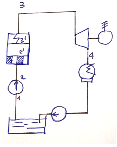
The Hirn cycle
Compared to the Rankine cycle, the Hirn cycle has one fundamental modification.
The limits of the Rankine cycle are overcome in the Hirn cycle by superheating the saturated vapor exiting the vaporizer. In this way, the serious problems of wear of the turbine and its unsatisfactory performance generated by the Rankine cycle can be avoided.
What fits into the Hirn cycle
A third heat exchange phase is inserted into the steam generator, carried out by an exchanger called a superheater, allowing, compared to a Rankine cycle, to have a higher steam content at the turbine exit.
Conclusions
The best-known thermodynamic cycle is the Carnot cycle, but it is an ideal cycle. Rankine and Hirn cycles try to better photograph the reality of machines that carry out thermodynamic transformations.
Request
Have you ever heard of one of these three cycles, i.e. the Carnot, Rankine or Hirn cycle?
![]()
ITALIAN
08-07-2024 - Sistemi energetici - Cicli termodinamici[EN]-[IT]
Cicli termodinamici
Diagramma T-s
Qui di seguito è mostrato il diagramma T-s del ciclo di Carnot
Schema impianto
Qui di seguito lo schema dell’impianto che potrebbe costituire il riferimento ideale al diagramma proposto sopra.
Il ciclo di Carnot
Il ciclo di Carnot è un modello ideale che rappresenta una macchina termica. Questa macchina termica quindi è una macchina termica ideale che opera con la massima efficienza possibile tra due riserve di calore (un serbatoio con una temperatura maggiore ed un serbatoio con una temperatura inferiore)
Il ciclo è composto di 4 fasi qui sotto elencate:
-Espansione isoterma
-Espansione adiabatica
-Compressione isoterma
-Compressione adiabatica
Se guardiamo il ciclo sul grafico T-s, temperatura-entropia, possiamo identificare le 4 fasi come segue:
1-2 compressione isoentropica. Dove sii ha un aumento di pressione ed il fluido esce in condizioni di liquido saturo.
2-3 generatore di vapore. Dove il fluido attraversa uno scambiatore attraverso il quale riceve calore dalla sorgente termica ed esce in condizioni di vapore saturo,
3-4 espansione isoentropica. Qui il fluido produce lavoro e viene fornito ad un utilizzatore esterno,
4-1 condensatore. Fase in cui il fluido attraversa uno scambiatore attraverso il quale cede calore al pozzo termico.
Diagramma T-s, Rankine
Qui di seguito è mostrato il diagramma T-s del ciclo di Rankine
Schema impianto
Qui di seguito lo schema dell’impianto che potrebbe costituire il riferimento ideale al diagramma proposto sopra che fa riferimento al ciclo di Rankine.
Il ciclo di Rankine
Il ciclo di Rankine è simile a quello di Carnot ma ci sono alcune differenze importanti.
Qui di seguito sono descritte le principali differenze che ci sono tra il ciclo di Carnot e quello Rankine.
Qui di seguito le modifiche, quindi cosa c’è di diverso rispetto al ciclo di Carnot
-Durante la condensazione il fluido in uscita arriva nelle condizioni di liquido saturo.
-La fase di compressione diventa una fase di pompaggio del liquido saturo. Questo comporta che in uscita dalla fase di pompaggio non avrò liquido saturo come nel caso precedente, ma liquido sottoraffreddato.
-il generatore di vapore, oltre a vaporizzare il fluido, dovrà anche fornire calore per portare il liquido sottoraffreddato in condizioni di saturazione. Questo scambiatore è detto anche economizzatore o preriscaldatore ed effettua la trasformazione 2-2’
Diagramma T-s, Hirn
Qui di seguito è mostrato il diagramma T-s del ciclo di Rankine
Schema impianto
Qui di seguito lo schema dell’impianto che potrebbe costituire il riferimento ideale al diagramma proposto sopra che fa riferimento al ciclo di Hirn
Il ciclo di Hirn
Rispetto al ciclo Rankine, il ciclo di Hirn ha una modifica fondamentale.
I limiti del ciclo Rankine vengono superati nel ciclo di Hirn facendo surriscaldare il vapore saturo in uscita dal vaporizzatore. Così si possono evitare i gravi problemi di usura della turbina e un rendimento insoddisfacente della stessa generato appunto dal ciclo di Rankine.
Cosa si inserisce nel ciclo di Hirn
Nel generatore di vapore viene inserita una terza fase di scambio termico, effettuata da uno scambiatore detto surriscaldatore consentendo, rispetto ad un ciclo Rankine, di avere un titolo di vapore più elevato all’uscita della turbina.
Conclusioni
Il ciclo termodinamico più conosciuto è il ciclo di Carnot, ma è un ciclo ideale. I cicli di Rankine e Hirn cercano di fotografare meglio la realtà delle macchine che compiono trasformazioni termodinamiche.
Domanda
Avete mai sentito parlare di uno di questi tre cicli, cioè del ciclo di Carnot, Rankine o Hirn?
THE END
Congratulations @stefano.massari! You have completed the following achievement on the Hive blockchain And have been rewarded with New badge(s)
You can view your badges on your board and compare yourself to others in the Ranking
If you no longer want to receive notifications, reply to this comment with the word
STOPCheck out our last posts:
Thanks for the topic
Are those three the only thermodynamic circles that are existing?
The Carnot cycle is quite popular
Don’t know much about the rest…
The Carnot cycle is cool because it's the gold standard for efficiency. The Rankine and Hirn cycles seem really practical for real-world applications.