[ESP/ENG] Compuerta NOT: Simplicidad y Poder en la Inversión Lógica 🔄🚀NOT Gate: Simplicity and Power in Logical Inversion
[ESP]
¡Saludos, vibrante comunidad de Hive! 👋
Continuamos nuestra serie sobre las puertas lógicas con un componente esencial en la electrónica digital: la Compuerta NOT. Esta compuerta, también conocida como inversor, juega un papel crucial en el procesamiento de señales al invertir su estado lógico. 🖥️✨
¿Qué es una Compuerta NOT? 🤔
La compuerta NOT es un circuito lógico que tiene una única entrada y una única salida. Su función es simple: invertir el estado lógico de su entrada. Si la entrada es alta (1), la salida será baja (0), y viceversa.
Funcionamiento Básico ⚙️
- Entrada: Una entrada que acepta una señal binaria (0 o 1).
- Salida: Una salida que es el inverso de la entrada.
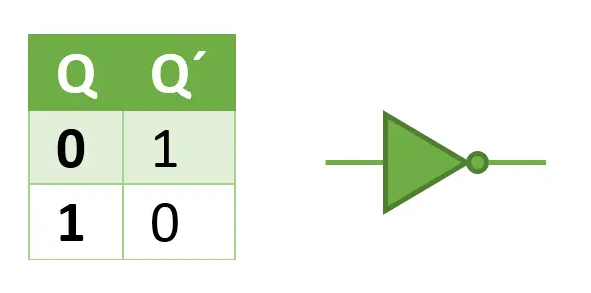
Símbolo y Tabla de Verdad 📊
El símbolo de la compuerta NOT se representa como un triángulo apuntando hacia un círculo. La tabla de verdad para la compuerta NOT es la siguiente:
Aplicaciones Prácticas 🌍
- Control de Lógica: Usada para cambiar estados de control en circuitos digitales, esencial en lógicas complejas y sistemas computacionales.
- Circuitos de Oscilación: En combinación con otras puertas, la compuerta NOT puede formar osciladores y temporizadores.
- Sistemas de Memoria: Fundamental en el diseño de flip-flops y memorias, donde se requiere la inversión de señales para el almacenamiento y procesamiento de datos.
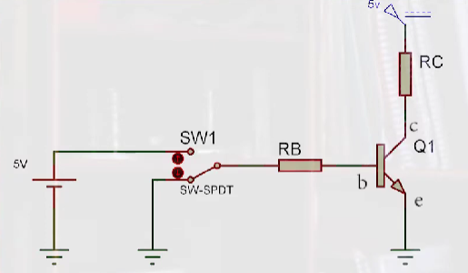
Construyendo un Circuito NOT Básico 🔧
Para los entusiastas que desean experimentar:
- Componentes Necesarios: Un transistor y una resistencia.
- Montaje: El transistor se utiliza para crear el efecto de inversión cuando se activa, bloqueando o permitiendo el paso de la corriente según la señal de entrada.
📢 ¡Gracias por descubrir conmigo esta puerta lógica esencial! 📘
Espero que este post sobre la compuerta NOT te haya proporcionado una visión clara de su importancia y te inspire a integrarla en tus proyectos de electrónica digital. Si te ha resultado útil, comparte tus pensamientos y no dudes en comentar. 📝
🔔 Mantente conectado para más publicaciones donde exploraremos más componentes electrónicos y sus aplicaciones. 🌐
🤝 Únete a nuestra comunidad en redes sociales para más interacciones y aprendizaje colaborativo. ¡Tu participación enriquece nuestra experiencia colectiva! 💬
📷 Comparte tus proyectos: Si has implementado una compuerta NOT o cualquier otra lógica en tus diseños, ¡muéstranos! Tu creatividad fortalece nuestra comunidad. 🛠️
🌟 Sigue conectado: No olvides seguirme para actualizaciones, contenido exclusivo y consejos prácticos en electrónica y circuitos. ¡Juntos hacemos que la electrónica sea accesible y emocionante para todos! 🚀✨
¡Hasta la próxima, sigue innovando y compartiendo tus logros!
[ENG]
Greetings, vibrant Hive community! 👋
We continue our series on logic gates with an essential component in digital electronics: the NOT Gate. This gate, also known as an inverter, plays a crucial role in signal processing by inverting its logical state. 🖥️✨
What is a NOT Gate? 🤔
The NOT gate is a logic circuit that has a single input and a single output. Its function is simple: to invert the logical state of its input. If the input is high (1), the output will be low (0), and vice versa.
Basic Operation ⚙️
- Input: An input that accepts a binary signal (0 or 1).
- Output: An output that is the inverse of the input.
Symbol and Truth Table 📊
The NOT gate symbol is represented as a triangle pointing towards a circle. The truth table for the NOT gate is as follows:
Practical Applications 🌍
- Logic Control: Used to change control states in digital circuits, essential in complex logic and computer systems.
- Oscillation Circuits: In combination with other gates, the NOT gate can form oscillators and timers.
- Memory Systems: Fundamental in the design of flip-flops and memories, where signal inversion is required for data storage and processing.
Building a Basic NOT Circuit 🔧
For enthusiasts who want to experiment:
- Components Required: A transistor and a resistor.
- Assembly: The transistor is used to create the inversion effect when turned on, blocking or allowing current to pass depending on the input signal.
📢 Thank you for discovering this essential logic gate with me! 📘
I hope this post about the NOT gate has given you a clear insight into its importance and inspires you to integrate it into your digital electronics projects. If you found it useful, please share your thoughts and feel free to comment. 📝
🔔 Stay tuned for more posts where we'll explore more electronic components and their applications. 🌐
🤝 Join our community on social media for more interactions and collaborative learning. Your participation enriches our collective experience! 💬
📷 Share your projects: If you've implemented a NOT gate or any other logic in your designs, show us! Your creativity strengthens our community. 🛠️
🌟 Stay tuned: Don't forget to follow me for updates, exclusive content, and practical tips on electronics and circuits. Together we make electronics accessible and exciting for everyone! 🚀✨
Until next time, keep innovating and sharing your achievements!
Congratulations @profwhitetower! You have completed the following achievement on the Hive blockchain And have been rewarded with New badge(s)
Your next target is to reach 60 posts.
You can view your badges on your board and compare yourself to others in the Ranking
If you no longer want to receive notifications, reply to this comment with the word
STOPCheck out our last posts:
Muy buen contenido amigo 👍🏼 . Me gustó mucho la forma en la que lo redactaste 👀
Me hiciste recordar mis clases de lógica en la universidad ❤️
Saludos!