[ESP/ENG] ¡Explora los Secretos del Filtro Pasa Banda y Transforma tu Experiencia Electrónica! 🎛️🔊 Explore the Secrets of the Bandpass Filter and Transform your Electronic Experience! 🎛️🔊
[ESP]
¡Hola, querida comunidad de Hive! 👋
En publicaciones anteriores, hemos explorado circuitos RC, RL, RLC en continua y alterna, resonancia y la constante de tiempo, tau. Hoy, vamos a sumergirnos en el fascinante mundo de los Filtros Pasa Banda. 🌊🎶
Introducción a los Filtros Pasa Banda 📚🔍
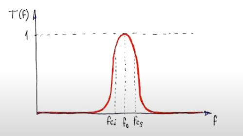
Un filtro pasa banda es un dispositivo que permite el paso de señales dentro de una determinada banda de frecuencias y atenúa las señales fuera de esa banda. Estos filtros son esenciales en muchas áreas de la electrónica y la comunicación, donde se necesita seleccionar o eliminar ciertas frecuencias. 📡📊
Características de los Filtros Pasa Banda
- Frecuencia de Corte Inferior fl: La frecuencia por debajo de la cual las señales son atenuadas.
- Frecuencia de Corte Superior fh: La frecuencia por encima de la cual las señales son atenuadas.
- Ancho de Banda (BW): La diferencia entre la frecuencia de corte superior e inferior fh - fl.
- Ganancia de Banda: La medida en que las señales dentro de la banda de paso son amplificadas o atenuadas.
- Aplicaciones: Utilizados en comunicaciones de radio, sistemas de audio, y equipos de prueba y medición.
Análisis de un Filtro Pasa Banda 🔬📈
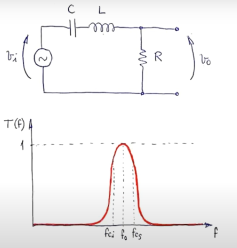
Un filtro pasa banda puede ser implementado usando diferentes configuraciones de circuitos, pero una de las más comunes es utilizando una combinación de circuitos LC (Inductor-Capacitor) en serie y paralelo. Analicemos su comportamiento en detalle:
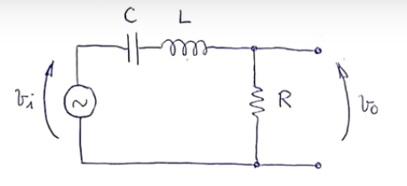
Circuito de Filtro Pasa Banda LC:
Consiste en un inductor (L) y un capacitor (C) en serie.
La salida se toma a través del circuito LC, lo que permite el paso de una banda específica de frecuencias.
Frecuencias de Corte fl y fh:
Las frecuencias de corte se calculan usando las siguientes fórmulas:
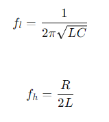
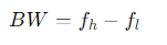
Ancho de Banda (BW):
El ancho de banda es la diferencia entre las frecuencias de corte superior e inferior:
Ganancia de Banda:
La ganancia en la banda de paso depende de los valores de L, C y R en el circuito.
Ejemplo Práctico 📐🔧
Supongamos que tenemos un filtro pasa banda con los siguientes valores:
- Resistencia (R): 10 Ω
- Inductancia (L): 2 mH
- Capacitancia (C): 100 nF
Para este filtro:
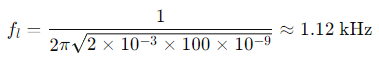
La frecuencia de corte inferior fl será:
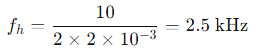
La frecuencia de corte superior fh será:
El ancho de banda (BW) será:
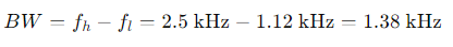
Esto significa que señales dentro de la banda de 1.12 kHz a 2.5 kHz pasarán con mínima atenuación, mientras que señales fuera de esta banda serán atenuadas.
Aplicaciones Comunes 🌐🔊
- Comunicaciones de Radio: Para seleccionar señales de una banda específica y rechazar otras.
- Sistemas de Audio: Para filtrar frecuencias no deseadas y mejorar la calidad del sonido.
- Instrumentación y Medición: Para aislar frecuencias específicas en equipos de prueba y medición.
📢 ¡Gracias por leer! Mantente conectado para más contenido educativo 📚
Espero que este post te haya sido útil. Si fue así, no olvides dejar un comentario y compartir tus pensamientos o preguntas. 📝
🔔 No te pierdas mis próximas publicaciones donde seguiremos explorando el fascinante mundo de la electrónica y los circuitos. Cada semana, voy a traer nuevos temas, ejemplos prácticos y recursos para que sigas aprendiendo y mejorando tus habilidades.
🤝 Sígueme en mis redes sociales, donde podrás conectarte con otros entusiastas de la electrónica, hacer preguntas y recibir ayuda en tiempo real. ¡Estamos aquí para ayudarte!
📷 Comparte tus proyectos: Si has aplicado estos conocimientos en tus propios proyectos, ¡nos encantaría verlos! Comparte tus avances y aprende de otros en nuestra comunidad.
🌟 Mantente en contacto: Sígueme en mis redes sociales para actualizaciones, contenido exclusivo y más consejos sobre electrónica y circuitos. Tu participación y apoyo son lo que hace que esta comunidad crezca y se enriquezca.
¡Nos estamos leyendo! Hasta entonces, sigue explorando, aprendiendo y compartiendo. ¡Juntos, hacemos la electrónica más accesible y emocionante para todos! 🚀✨
[ENG]
Hello, dear Hive community! 👋
In previous posts, we have explored RC, RL, RLC circuits in DC and AC, resonance and the time constant, tau. Today, we are going to dive into the fascinating world of Band Pass Filters. 🌊🎶
Introduction to Band Pass Filters 📚🔍
A band pass filter is a device that allows signals within a certain frequency band to pass and attenuates signals outside that band. These filters are essential in many areas of electronics and communication, where certain frequencies need to be selected or eliminated. 📡📊
Characteristics of Band Pass Filters
- Lower Cutoff Frequency fl: The frequency below which signals are attenuated.
- Upper Cutoff Frequency fh: The frequency above which signals are attenuated.
- Bandwidth (BW): The difference between the upper and lower cutoff frequency fh - fl.
- Band Gain: The extent to which signals within the passband are amplified or attenuated.
- Applications: Used in radio communications, audio systems, and test and measurement equipment.
Analysis of a Band Pass Filter 🔬📈
A bandpass filter can be implemented using different circuit configurations, but one of the most common is using a combination of series and parallel LC (Inductor-Capacitor) circuits. Let's analyze its behavior in detail:
LC Bandpass Filter Circuit:
It consists of an inductor (L) and a capacitor (C) in series.
The output is taken through the LC circuit, allowing a specific band of frequencies to pass through.
Cutoff Frequencies fl and fh:
Cutoff frequencies are calculated using the following formulas:
Bandwidth (BW):
Bandwidth is the difference between the upper and lower cutoff frequencies:
Band Gain:
The gain in the passband depends on the values of L, C and R in the circuit.
Practical Example 📐🔧
Suppose we have a bandpass filter with the following values:
- Resistance (R): 10 Ω
- Inductance (L): 2 mH
- Capacitance (C): 100 nF
For this filter:
The lower cutoff frequency fl will be:
The upper cutoff frequency fh will be:
The bandwidth (BW) will be:
This means that signals within the 1.12 kHz to 2.5 kHz band will pass with minimal attenuation, while signals outside this band will be attenuated.
Common Applications 🌐🔊
- Radio Communications: To select signals from a specific band and reject others.
- Audio Systems: To filter unwanted frequencies and improve sound quality.
- Instrumentation and Measurement: To isolate specific frequencies in test and measurement equipment.
📢 Thanks for reading! Stay tuned for more educational content 📚
I hope this post has been useful to you. If so, don't forget to leave a comment and share your thoughts or questions. 📝
🔔 Don't miss my next posts where we will continue exploring the fascinating world of electronics and circuits. Each week, I'll bring new topics, practical examples, and resources to keep you learning and improving your skills.
🤝 Follow me on my social networks, where you can connect with other electronics enthusiasts, ask questions and receive help in real time. We are here to help you!
📷 Share your projects: If you have applied this knowledge in your own projects, we would love to see them! Share your progress and learn from others in our community.
🌟 Stay in touch: Follow me on my social networks for updates, exclusive content and more tips on electronics and circuits. Your participation and support are what make this community grow and enrich.
We are reading each other! Until then, keep exploring, learning and sharing. Together, we make electronics more accessible and exciting for everyone! 🚀✨
Congratulations @profwhitetower! You have completed the following achievement on the Hive blockchain And have been rewarded with New badge(s)
Your next target is to reach 4250 upvotes.
You can view your badges on your board and compare yourself to others in the Ranking
If you no longer want to receive notifications, reply to this comment with the word
STOPCheck out our last posts:
Thanks for your contribution to the STEMsocial community. Feel free to join us on discord to get to know the rest of us!
Please consider delegating to the @stemsocial account (85% of the curation rewards are returned).
You may also include @stemsocial as a beneficiary of the rewards of this post to get a stronger support.
Short and clear explanation! With this post you brought me to my student years!
Hello! 😊
Thank you very much for your comment. I'm glad to know that my explanation brought back good memories of your student years. How nice to know that this content can connect with past experiences and bring a little educational nostalgia! 📚✨
Greetings,