🔧📱 Samsung Galaxy J2 Prime with Charging Failure. Diagnosis and Repair / Movil Samsung Galaxy J2 Prime con falla de carga.Diagnóstico y reparación ⚡🔍🛠️

Good afternoon to this great @geekzone community and also to the rest of Hive.
Buenas tardes para toda esta gran comunidad @geekzone y también para el resto de Hive.
Today we present another repair from our workshop, in this case, a Samsung J2 Prime mobile phone that does not charge. We are going to proceed as always; these failures are very, very common in our workshop. We will carry out the diagnosis, and then the repair if it is within our capabilities.
Hoy les presentamos otra reparación en el taller, en este caso, un móvil Samsung J2 Prime que no carga. Vamos a proceder como siempre, estas fallas son muy, muy comunes en nuestro taller. Realizaremos el diagnóstico, y luego la reparación si está a nuestro alcance.


DIAGNOSIS
DIAGNÓSTICO
1-We are going to use our power supply as a USB tester. We set it to 5.13 V and 2 A and connect the USB cable to our mobile phone. As we can see, the current reading is zero on the display of our power supply. This means that, in fact, there is not the slightest flow of electrons into the phone, indicating that it is indeed not charging. In addition, this zero value also indicates that current is not even reaching the charging stage of the IC. I want to emphasize that, for this case, the power supply is set to 5.13 V because this is the voltage delivered by a conventional charger at the input of the phone's USB port. When we connect the power supply to the battery connector on the mobile phone, it should be set to 4.2 V, which is the maximum working voltage of that line.
1-Vamos a usar nuestra fuente de poder como tester USB, la configuramos a 5.13 V y 2 A y conectamos el cable USB a nuestro móvil. Como vemos, la lectura de corriente es cero en la pizarra de nuestra fuente. Significa que, en efecto, no hay el más mínimo flujo de electrones hacia el interior del teléfono, indicando que, en efecto, no carga. Además, este valor cero indica también que no está llegando la corriente ni siquiera a la etapa de carga del IC. Quiero recalcar que la fuente para este caso se regula a 5.13 V porque es el voltaje que entrega un cargador convencional a la entrada del puerto USB del teléfono. Cuando conectamos la fuente al conector de la batería en el móvil, sí se regulará a 4.2 V, que es el máximo voltaje de trabajo de esa línea.

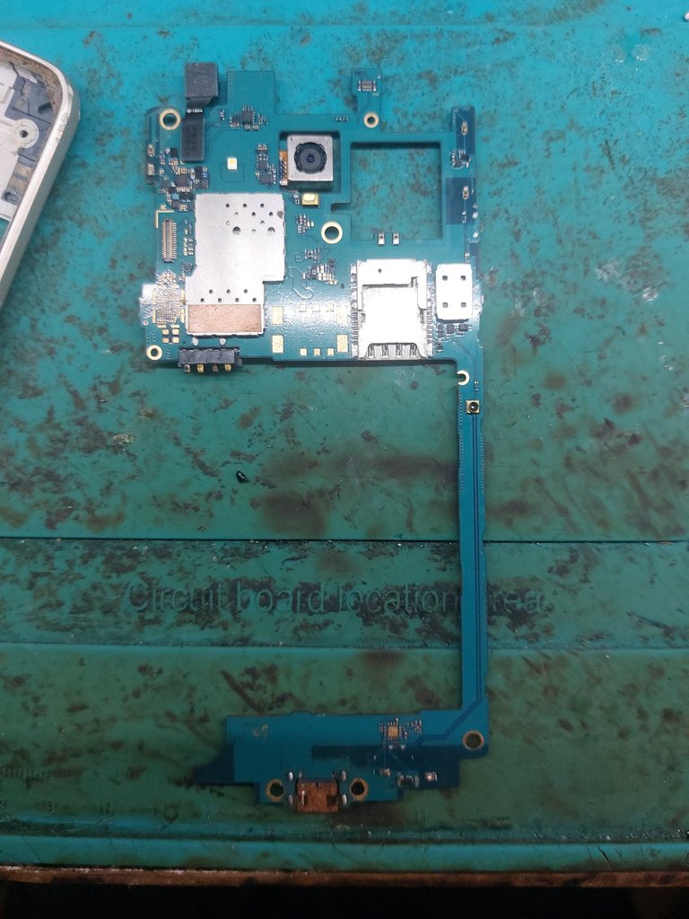
2-A priori, we already suspect that the charging port must be damaged. Now we are going to open the mobile phone to confirm our suspicion. This model is not one of the most difficult phones to open, but it is not one of the easiest either, especially when the screen is cracked. Since we notice that it has already been opened previously, we will not apply heat. First, we will remove all the screws from the back. Now, with a small plastic opening tool, we insert it around the edges of the phone between the frame and the screen, and carefully slide it all the way around. Finally, we manage to open it and completely remove the board.
2-A priori, ya sospechamos que debe estar dañado el puerto de carga, ahora vamos a abrir el móvil para corroborar nuestra sospecha. Este modelo de móvil no es de los más difíciles de abrir, pero tampoco es de los más sencillos, más cuando la pantalla está cuarteada. Como notamos que ya se ha abierto con antelación, no aplicaremos calor. Quitaremos primero todos los tornillos de la parte trasera. Ahora, con un pequeño abridor plástico, lo introducimos por los bordes del teléfono entre el marco y la pantalla, y lo vamos deslizando con cuidado a todo lo largo. Finalmente, se logra abrir, y retiramos completamente la board.



3-We will take a new measurement, but this time with the multimeter. We will start with the least complex step, which is measuring whether we have 5.2 volts on the USB port pins. We connect the cable to the mobile phone, set the multimeter to the DC voltage scale, with the positive probe on one end of the pin and the negative probe on the other end. The two outer pins will always be the negative and positive terminals. If we place the multimeter probes incorrectly according to the polarity, what will happen is that we will obtain a negative voltage value, but the measurement is still correct. In this case, our measurement gives us a value of 1.527 V, so the problem is identified here. Instead of the expected 4.2 V, only 1.527 V is entering. Logically, no voltage will reach the battery connector and, therefore, the mobile phone will not charge. As a final diagnosis, we confirm that the charging port is internally damaged.
3-Realizaremos una nueva medición, pero ahora con el multímetro, empezaremos por lo menos complejo que es medir si tenemos los 5.2 volt en los pines del puerto USB. Conectamos el cable al móvil, colocamos el multímetro en escala de voltaje continuo, punta positiva a un extremo del pin, punta negativa al otro extremo. Los dos pines extremos siempre serán el negativo y el positivo, si colocamos mal las puntas del multímetro según la polaridad, lo que sucederá es que tendremos el valor de voltaje negativo, pero modularmente es correcto. En este caso, nuestra medición nos arroja un valor de 1.527 V, así que aquí queda identificado el problema, de un valor que debe existir de 4.2 V, solo entran 1.527 V, lógicamente, no llegará nada de voltaje al conector de la batería y, por ende, el móvil no cargará. Como diagnóstico final, corroboramos que el puerto de carga está dañado internamente.


REPAIR
>REPARACIÓN
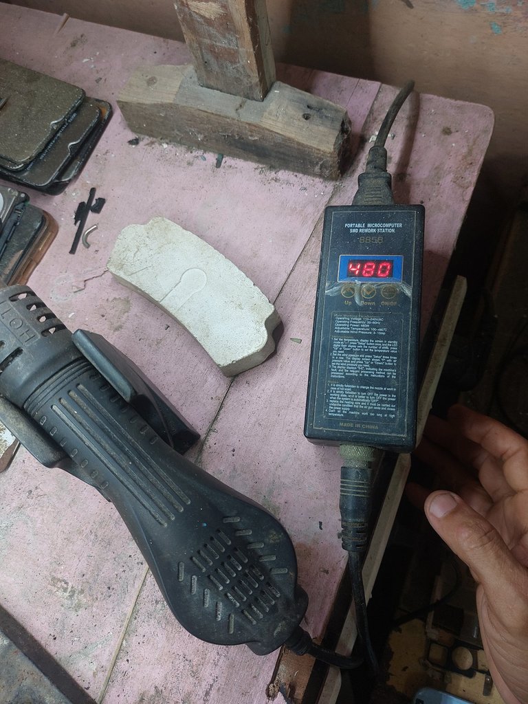
1-The repair consists of replacing the port with a new one. This component is not repaired; it is replaced. We have done this many times. We will place our board in the elevated board holder, set our hot air station to 480 degrees, and with the help of the soldering iron, apply heat to the pins and the middle of the port until it can be removed from the board. We can accomplish this in just 40 to 60 seconds.
1-La reparación consiste en cambiar el puerto por uno nuevo. Esta pieza no se repara, sino que se cambia. Esto lo hemos hecho muchísimas veces. Pondremos nuestra board en el sujetador de placas elevado, regularemos nuestra estación de calor a 480 grados y, con ayuda del cautín, daremos calor en los pines y el medio del puerto hasta desmontarlo de la placa. Esto lo logramos en apenas 40 a 60 segundos.




2-Next, we will clean the four holes where the anchors are located, since when the port is removed, they are always sealed with residual solder. We will use the solder sucker and the soldering iron. With the soldering iron set to approximately 350 degrees, we will place the tip in one of the anchor holes on the upper part until the solder covering it melts. Then, with the solder sucker on the lower side, we activate it and remove the hot solder, leaving the hole clean. We repeat this process for the remaining three holes. On other occasions, we have used a combination of the soldering iron and desoldering braid, which is also a valid technique.
2-Seguido, vamos a limpiar los cuatro orificios donde van los anclajes, pues al extraer el puerto siempre quedan sellados con estaño residual. Nos auxiliaremos del extractor de estaño y el cautín. Con este, regulado a unos 350 grados, colocaremos la punta en uno de los agujeros del anclaje de la parte superior, hasta derretir el estaño que lo cubre, luego con el extractor de estaño por la parte inferior, lo accionamos y extrae el estaño caliente, dejando limpio el agujero. Repetimos este proceso para los tres restantes agujeros. En otras ocasiones hemos usado la combinación del cautín y la malla de soldadora, que es otra técnica válida también.


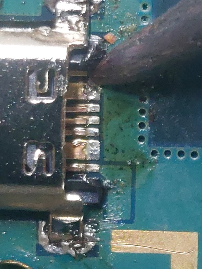
3-We go over the rear pins on the board where the charging port will be placed, install the new port, solder the four anchors, check the contact between the port pins and the contacts on the board, and that's it. The new port is now installed.
3-Repasamos los pines traseros en la placa donde se apoyará el puerto de carga, colocamos el nuevo puerto, soldamos los cuatro anclajes, rectificamos el contacto entre los pines del puerto y los contactos en la placa y listo, el nuevo puerto ya está montado.


4-We will take a new measurement with the power supply. We will set it to 5 V and 2 A as before, connect the cable to the mobile phone with the new port, and we have the first positive result. We get a reading of 0.082, 0.093 V. This small consumption means that current has entered the charging circuit and it is trying to find the battery.
4-Realizaremos una nueva medición con fuente, vamos a colocarla igual en 5 V y 2 A, conectamos el cable al móvil con el nuevo puerto, y tenemos el primer resultado positivo, tenemos una lectura de 0.082, 0.093 V, este pequeño consumo significa que ha ingresado corriente al circuito de carga y está tratando de encontrar la batería.


5-We will carry out a second measurement, now with the multimeter, set to the DC voltage scale. We measure at the battery connector and that's it. We have 4.26 V. With this voltage, the battery will charge.
5-Realizaremos una segunda medición, ahora con el multímetro, en escala de voltaje continuo, medimos en el conector de la batería y listo. Tenemos 4.26 V. Con este voltaje, la batería sí cargará.

6-We assemble the mobile phone, connect the battery, and repeat the test with the power supply. Now we do have a correct measurement: 0.358 Amperes, meaning that this current value is entering the battery. Problem solved, ready to deliver to the customer.
6-Armamos el móvil, conectamos la batería, y repetimos la prueba con fuente. Ahora sí tenemos una medida correcta, 0.358 Amperes, significando que este valor de corriente está ingresando a la batería. Problema resuelto, listo para entregar al cliente.


That is all for this repair. I hope you found it interesting. Thank you to all the readers for your attention. All images and writing are entirely my own.
Hasta aquí, esta reparación. Espero les haya sido de interés. Gracias a los lectores por su atención. Todas las imágenes y redacción son de mi total autoría.
Translated with the help of Google Translate.
Traducido con ayuda del traductor de Google.
Until next time.
Hasta pronto
Son como lo peor en la gama de Samsung pero entiendo que algunos tenemos el celular que se puede y lo arreglaste muy bien
Exacto. Este modelo el G532 fue muy famoso entre los técnicos. Se quedaba pegado en el Logo de inicio. Y cuando lo flasheabas, o se le montaba el sistema operativo se quedaba muerto y sin encender. Había que revivirlo con la técnica del ISP que solo contados técnicos tenian equipos para hacerla. No obstante, aun quedan algunos de estos ejemplares con casi 10 años de explotación, y de echo hay otros aun mas antiguos. Ciertamente, muchas personas en mi país no tienen nisiquiera para uno aunque sea viejo. Saludos, gracias por leer el post.
Thanks for your contribution to the STEMsocial community. Feel free to join us on discord to get to know the rest of us!
Please consider delegating to the @stemsocial account (85% of the curation rewards are returned).
Thanks for including @stemsocial as a beneficiary of this post and your support for promoting science and education on Hive.