Understanding Operational Amplifier with Experiment
Operational amplifiers or op-amps are one of the most common circuit components in analog electronic circuits. They're simple to operate and can produce near-perfect analog circuits. The op-amp is a differential amplifier circuit block that allows several different electronic amplifier circuits to be constructed with just a few other components. The operational amplifier may be used to build a variety of circuits, like filters, timers, oscillators, and comparators. As a result, the operational amplifier is one of the most useful building blocks for analog electronics circuit designers and hobbyists. The first monolithic integrated circuit op-amp was released in 1963. Fairchild Semiconductor's 1702, engineered by their engineer Bob Widlar, was the device in question.
The Basic Op-Amp
The Operational Amplifier is widely used for changing the voltage amplitude which includes the amplitude and polarity, oscillators, filter circuits, and other types of instrumentation circuits. An Op-Amp is usually consisting of 2 input terminal and 1 output terminal. The 2-input terminal is having a positive terminal which is called the non-inverting terminal and the negative terminal is called the inverting terminal . The third terminal is the output terminal which has four classification of operational amplifier gain which are the voltage, current, transconductance, and transresistance. The voltage Op-Amp gain means that it has a voltage input and a voltage output while the current Op-Amp gain has the input current and the output is also a current.
The inverting input is denoted with a minus sign, while the non-inverting input uses a positive sign. Additionally, operational amplifiers may be classified into four ways. First, voltage amplifiers take in voltage and produce voltage at the output. Second, current amplifiers receive a current input and also produce a current output. Third, the transconductance amplifiers convert voltage input into a current output. And finally, Transresistance amplifiers convert current input and then produce voltage output.
Being arguably the most useful single device in the analog electric circuit, with just a few external parts, they can be made to perform a wide range of analog signal processing tasks. It is also quite affordable, and the most general-purpose amplifiers. Modern designs nowadays have been engineered with durability in mind as well as there are several op-amps being manufactured that can sustain direct short circuits on their outputs without damage.
An ideal amplifier has infinite gain, infinite input impedance, and zero output impedance, and an operational amplifier is a near approximation to one. In fact, op-amps do not quite achieve perfection, but with gains of 100 000 or more, input impedance levels of Megohms or more, and very low output impedance levels, they come close enough to allow flaws to be overlooked in most cases. There are two inputs on the operational amplifier. Since the output is proportional to the difference in voltage between the two inputs, the op-amp is essentially a differential amplifier
If the same voltage is applied to both inputs simultaneously, the output should remain unchanged. In fact, the difference between the inverting and noninverting inputs determines the output. As a result, these amplifiers are often referred to as differential amplifiers. A power supply is needed for those who use operational amplifiers. Op-amps are usually powered by dual, or positive and negative, supplies. In many other instances, the operational amplifier's operation would only require five connections: inverting, non-inverting, output, and the two power rails. A total of three can be used on rare occasions. These are typically used for the "offset null" function. This is used to reduce any DC offsets that might exist, which can usually be ignored and left disconnected in most applications.
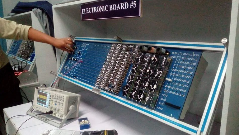
Experiment with Op-Amp
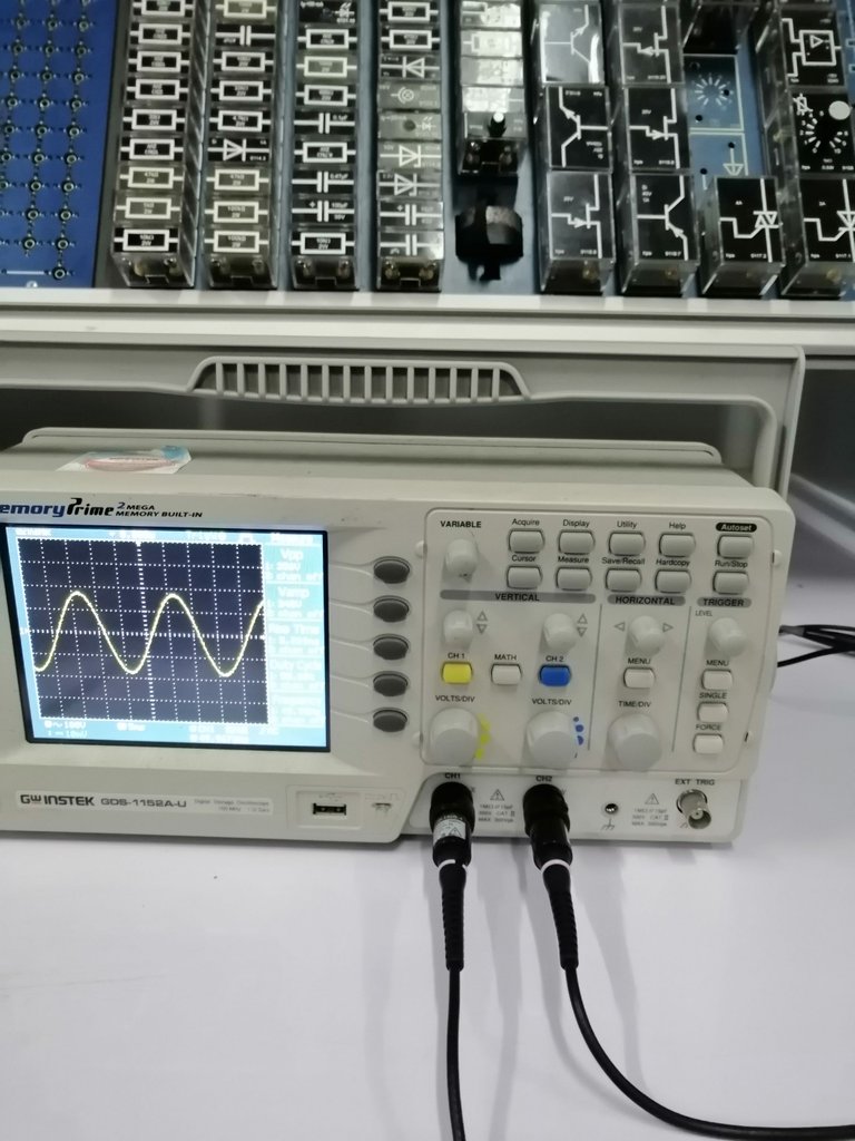
An oscilloscope showing a detected signal
For Inverting Operational Amplifier, the input signal is connected to the inverting input or the negative input terminal and the Non-Inverting input or the positive terminal is connected to the ground. In this configuration the inverting input receives a feedback coming from the output. A feedback is like a recirculation valve that delivers some part of the output back to the inverting input thus we expect a reduction in the amplifier’s gain. We can noticed that whenever there is an increase of the feedback resistance value given that the initial resistance value remains constant the gain will vary depending on the feedback.
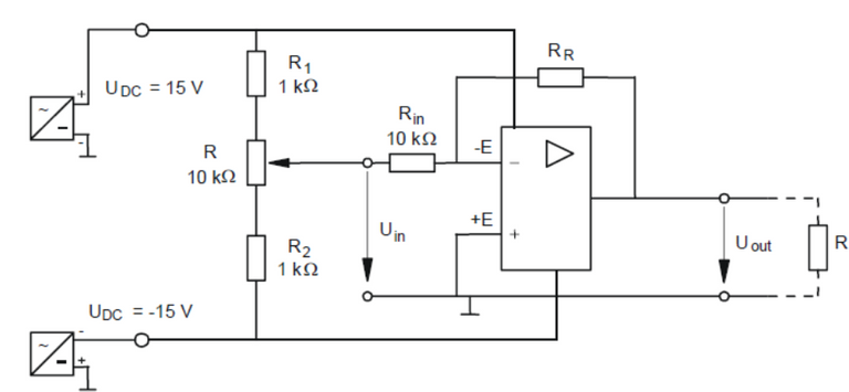
Inverting Op-Amp Circuit
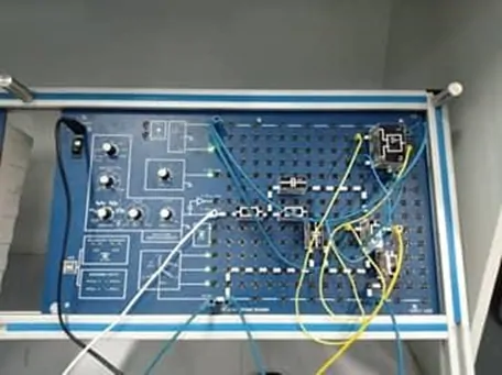
The actual circuit configured on an experiment board.
The DC source is connected to two resistor (R1 and R2) that is used to provide the necessary feedback across the op-amp circuit and is connected to the negative terminal of the operational amplifier. The R2 is also directly connected to the third terminal of the operational amplifier. The positive terminal of the amplifier on the other hand is connected to the ground directly, without any other electrical components connected to it
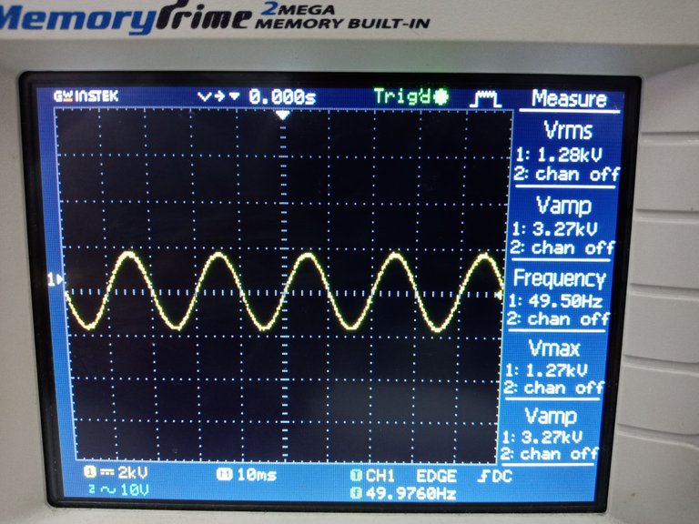
When we have higher feedback resistance, the amplifier gain increases but will be negative. The negative does not denote losses, but it indicates that it is in inverting effect. When we plot the output signal in the oscilloscope, we get a sinusoidal wave in the output and amplified to the calibrated gain. The plot shown migth be a little distorted due to inherent harmonics in the our board (due to welding lab in operation). Nevertheless, we get the expected inverting effect and that indicates that we achieve the goal of the configuration.
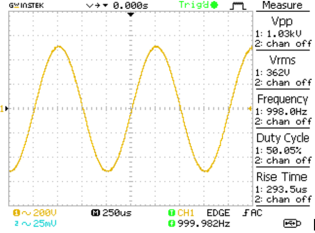
The input signal recoded from the oscilloscope
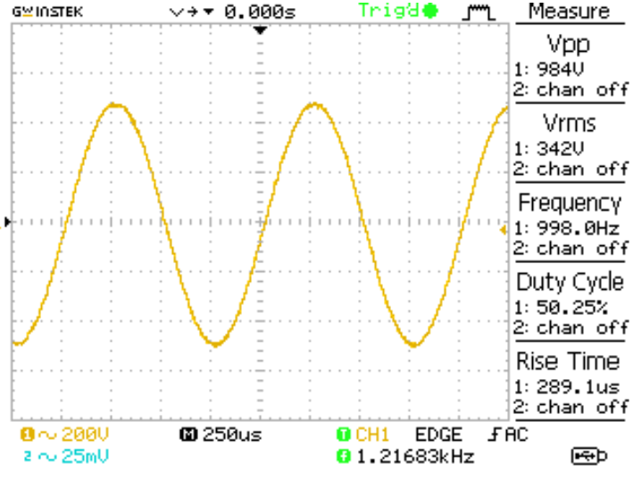
The output signal from the oscilloscope
For Non-Inverting Operational Amplifier, the input signal is feed to the Non-inverting Input or to the positive input terminal and the Inverting input or the negative input terminal input is connected to the ground. This is the complete opposite of the previous configuration because in terms of expected graph output and also the gain value in relation to the feedback resistance value. The non-inverting operational amplifier circuit configuration produced an amplified output signal, which, not like the inverting circuit, the output signal of the non-inverting op-amp is in phase with the input signal applied. But instead of connecting the input voltage in the negative terminal of the op-amp, it is connected to the positive terminal of the op-amp. And the two resistor is now still connected to the negative terminal of the op-amp but it is also connected before the ground.
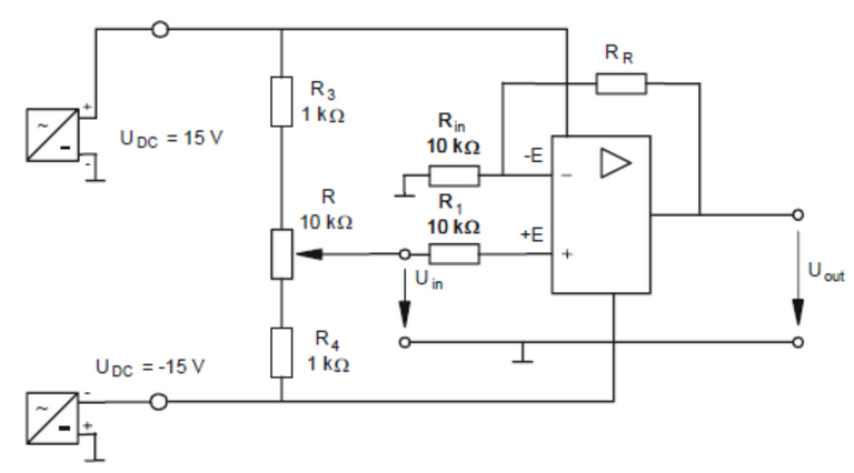
The Non-inverting Op-Amp Circuit

The input signal recoded from the oscilloscope
The output signal shown in the oscilloscope
The only difference is that the Non-inverting input or the positive input of the device is getting a feedback from the output thus having a positive gain. When we get the graph, we expected a result of a non-inverting sinusoidal wave. Additionally, the gain in this configuration is much higher than the previous configuration because of the positive feedback coming from the output.
References
- Boylestad and Nachelsky, Electronic Devices and Circuit Theory
- Floyd, Electronics Fundamentals. Circuits, Devices, and Applications
- Schultz, Grob’s Basic Electronics
Note:
All images are from the author except with separate citation.
https://twitter.com/juecoree/status/1381960895618674698
Thanks for your contribution to the STEMsocial community. Feel free to join us on discord to get to know the rest of us!
Please consider supporting our funding proposal, approving our witness (@stem.witness) or delegating to the @stemsocial account (for some ROI).
Please consider using the STEMsocial app app and including @stemsocial as a beneficiary to get a stronger support.
Your post has been voted as a part of Encouragement program. Keep up the good work!
Try https://ecency.com and Earn Points in every action (being online, posting, commenting, reblog, vote and more).
Boost your earnings, double reward, double fun! 😉
Support Ecency, in our mission:
Ecency: https://ecency.com/proposals/141
Hivesigner: Vote for Proposal
Congratulations @juecoree! You have completed the following achievement on the Hive blockchain and have been rewarded with new badge(s) :
Your next payout target is 4000 HP.
The unit is Hive Power equivalent because your rewards can be split into HP and HBD
You can view your badges on your board and compare yourself to others in the Ranking
If you no longer want to receive notifications, reply to this comment with the word
STOPSupport the HiveBuzz project. Vote for our proposal!