Using Interruptions and PWM signals with the Timer 2 - Usando interrupciones y señales PWM con el Timer 2 - Microcontrollers # 13
Creating Frequencies
Shoutout to Circuit Digest

In this article you'll find:
- Introduction
- The Timer2
- Connections
- Program: Interruptions with Timer2
- Program: PWM pulse generator
Greetings to everyone and welcome back to another edition of Microcontrollers!
Again I apologize for the absence of more than a week. I had some personal issues to sort out, but here we are.
And that's where we left off that we will continue: In the previous article we learned about Timer1 and how we can use it to generate interrupts with a longer period of time. Now, we will see another timer.
In this case, we will observe Timer2 and its behavior, as well as its application in the most common scenarios: The generation of PWM pulses.
This way, we can begin!
Timer 2
Shoutout to MicrocontrollerBoard.com
If you have paid attention to the previous articles, then you will have no problem knowing how they work. These are simply responsible for counting the pulses generated either by an external element (being used as counters) or those generated by the internal clock of the microcontroller.
In the case of Timer 2, this is no exception to the rule. However, its use is what varies with respect to the others. Due to the high frequencies it can generate and its compatibility with a module known as CCP (Capture-Comparator-PWM), this Timer is used for frequency generation and pulse width modulation.
But what is pulse width modulation?
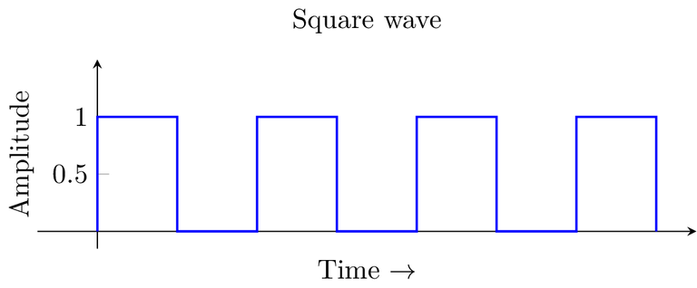
To understand it in detail, we have to observe the following sign:
Shoutout to Mathematica Stack Exchange
This is what is known as a square signal, where we have a period, which is the amount of time from the beginning of the signal until it returns to its initial state (In this case high).
During this period, we will have moments of time where the signal will be in a low state (logical 0) and others where it will be in a high state (logical 1). The amount of time in the period that the signal lasts in a high state is what is known as the Duty Cycle.
In the case of the image, the duty cycle is 50%, since during the period, 50% of the time the signal is high and the other 50% is low.
Now, the function of the PWM is to control this duty cycle, making the time that the signal lasts on longer or shorter. This is done both to send information and to control the amount of energy we send to the elements connected to the PIC.
If we take a light bulb as an example, we can vary its brightness intensity with the use of PWM. Looking at the following figure:
Shoutout to dotLib Creative Technology
Here, we notice that as the time the signal stays on increases (higher duty cycle), the brightness intensity of the bulb also increases. This is precisely what we are looking for by controlling the PWM. Whether it is the speed of a motor, the position of a servo or an LED, we control all this through PWM.
Now that we know Timer 2 works in conjunction with the CCP module to control the pulse width of a signal, we can verify the equations that allow us to make this possible in programming.
Thus, for the period of this Timer, we base ourselves on:
T = (PR2 + 1) * 4 * Fosc * Prescaler
And since we want PR2 (Number of pulses required for the Timer to overflow), we just have to clear it to obtain:
PR2 =   T * Fosc - 1
       ---------------
        4 * Prescaler
For Timer 2, we will only have 4 prescaler modes, which range from 1 to 16.
Reiterating that Timer 2 is used to generate frequencies, we can take an example that allows us to generate a frequency of 1kHz. Knowing that the frequency is determined by:
F =  1
    ---
     T
And if we solve to obtain the period:
T =  1
    ---
     F

T =    1
     ------
      1kHz

T = 1ms
However, something that we must keep in mind is that since Timer 2 is used very frequently for the PWM, we will only be interested in the time that the signal lasts on to assign the value to PR2. In this case, since the duty cycle will be 50% (Half of the time it will be on), we divide the value of T by 2, obtaining 0.5ms.
And now, by replacing T with 0.0005s (0.5ms) in the equation:
PR2 =  0.5ms * 20MHz - 1
      --------------
           4*16

PR2 =  0.5x10^-3 * 20x10^6 - 1
      --------------------
            4*16

PR2 = 155.25 = 155
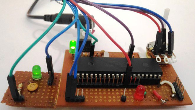
Connections
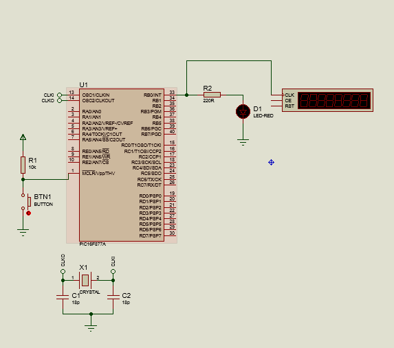
For the first connection we will do something simple. Since in the first program we only want to measure the 1kHz frequency generated by Timer 2, we will place only a red LED with its respective resistance next to a counter-timer, an instrument with which we can measure said frequency.
This would look like this:
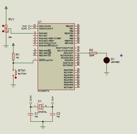
Regarding its use together with the PWM module, we will connect the CCP1 pin (RC2 PIN) to the same LED. In addition to this, we will connect the output of a potentiometer to the analog pin AN0. Looking at this:
Now that we know the connections of our program, we can move on to looking at the code.
Program: Interruptions with Timer2
For this first program, we will follow what was applied in the previous articles, using the #INT_TIMER2 tag and the setup_timer_2 instructions as well as enable_interrupts.
For setup_timer_2(), it will have 3 parameters, among which we will have:
- The prescaler mode, which can be: T2_DIV_BY_1 (Prescaler = 1), T2_DIV_BY_2(Prescaler = 2), T2_DIV_BY_4, T2_DIV_BY_8, T2_DIV_BY_16
- PR2, the value calculated with the equation.
- Postscaler, which is simply another frequency divider. Instead of being applied before the timer counts the pulses, it is applied to the output of the counter.
setup_timer_2(Prescaler Mode, PR2, Postscaler)
Thus, we write the first lines of our program, which refer to the header pins and determining port B as an input/output one. Likewise, we see that the interrupt function will only change the state of the output:
#include <16f877a.h>
#fuses HS, NOWDT, NOPROTECT, NOPUT, NOLVP, BROWNOUT
#use delay(clock=20M)
#use fast_io(B)

#INT_TIMER2
void interruption_function()
{
output_toggle(PIN_B0);
}
Then, in the void main() where we configure the program before executing the loop, we write:
void main()
{
    set_tris_b(0x00);
    setup_timer_2(T2_DIV_BY_16, 155, 1);
    enable_interrupts(INT_TIMER2);
    enable_interrupts(GLOBAL);
Here, we make the port B pins output (0x00), configure timer2 with a prescaler of 16, period for the frequency of 1kHz and a postscaler of 1.
We activate the interrupts for timer2 and the global ones and we are ready to execute. We leave the while loop empty since no instructions will be executed in the main program. Thus, looking at the complete program:
#include <16f877a.h>
#fuses HS, NOWDT, NOPROTECT, NOPUT, NOLVP, BROWNOUT
#use delay(clock=20M)
#use fast_io(B)

#INT_TIMER2
void interruption_function()
{
output_toggle(PIN_B0);
}

void main()
{
    set_tris_b(0x00);
    setup_timer_2(T2_DIV_BY_16, 155, 1);
    enable_interrupts(INT_TIMER2);
    enable_interrupts(GLOBAL);

    while(True)
    {

    }
}
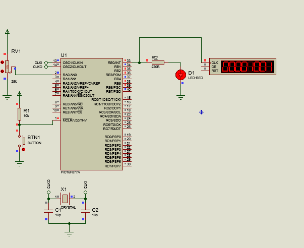
And when executed, placing the frequency counter on pin B0, we will have:
Program: PWM pulse generator
For our second program, since Timer 2 will be used as the clock behind the CCP module as a PWM and not as an interrupt, we will leave out the enable_interrupts and interrupt functions, leaving only setup_timer_2.
However, we must also take into account how to handle the CCP module, of which we can find two in our PIC microcontroller: CCP1 on pin C2 and CCP2 on pin C1.
To control this module, we must use the following instructions:
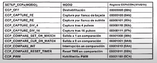
- set_ccp1() ; Where we configure the capture, comparison and PWM module in one of these modes. if we want to determine the mode of the CCP2 module, we just use set_ccp2();
- set_pwm1_duty() ; Determines the duty cycle on a scale of 0 to 255, with 0 being 0% and 255 being 100%. To assign the duty cycle to pwm 2, we use set_pwm2_duty();
The parameters that we can assign to set_ccp1 are numerous, but in this case, since what we are interested in is configuring it in PWM mode, this will be the one we use. If we look at the following image:
Shoutout to Electronics and Circuits
We have a perspective of the large number of parameters. Specifically, we will use the CCP_PWM.
Now, since we will control the duty cycle of a signal with an external element (The potentiometer), we will have to make use of the internal ADC converter of the PIC, so we will use the following initial lines of code:
#include <16f877a.h>
#deviceADC=10
#fuses HS, NOWDT, NOPROTECT, NOPUT, NOLVP, BROWNOUT
#use delay(clock=20M)
#include <map_function.c>

long adc_value;
int pwm_value;
Here, along with the configuration labels, we add that a 10-bit ADC will be used with device ADC=10 and we create two variables: One of type long, which will contain the values from 0 to 1024 of the ADC, and another of type integer that will contain values from 0 to 255, representing the duty cycle.
Now, looking at the void main()
void main()
{
    setup_adc_ports(AN0);
    setup_adc(adc_clock_internal);
    setup_timer_2(T2_DIV_BY_16, 155, 1);
    setup_ccp1(CCP_PWM);
We remember that with setup_adc_ports we determine the pin that we will use as the ADC channel, in this case being AN0. Additionally, with setup_adc we choose the ADC clock, being the internal clock of the PIC.
Thus, after configuring Timer 2 at a maximum time of 1ms (A frequency of 1kHz) with a prescaler of 16 and a postscaler of 1, we configure the CCP1 pin as PWM.
Then for the loop:
while(TRUE)
    {
       set_adc_channel(0);
       delay_us(2);
       adc_value = read_adc();
       pwm_value = map(adc_value, 0, 1024, 0, 255);

       set_pwm1_duty(pwm_value);
    }
}
Here, we choose the channel that we are going to read, which will be 0 (AN0), we wait a little for the instruction to be executed and we insert the value read from the potentiometer into the long type variable that we created with read_adc().
Then, with the map function, which allows us to convert a range of values into another, whether lower or higher, we make it so that instead of having values from 0 to 1024, it has values from 0 to 255, which meet the range for the integer type variables and for the PWM.
Finally, we assign the duty cycle to pwm1 based on what we obtain from pwm_value, so every time the potentiometer changes, we will also have a change in the PWM.
Thus, looking at the complete program:
#include <16f877a.h>
#deviceADC=10
#fuses HS, NOWDT, NOPROTECT, NOPUT, NOLVP, BROWNOUT
#use delay(clock=20M)
#include <map_function.c>

long adc_value;
int pwm_value;

void main()
{
    setup_adc_ports(AN0);
    setup_adc(adc_clock_internal);
    set_tris_b(0x00);
    setup_timer_2(T2_DIV_BY_16, 155, 1);
    setup_ccp1(CCP_PWM);


    while(TRUE)
    {
       set_adc_channel(0);
       delay_us(2);
       adc_value = read_adc();
       pwm_value = map(adc_value, 0, 1024, 0, 255);

       set_pwm1_duty(pwm_value);
    }
}
And executing:
Now, we already know a really important practical application for subsequent articles. Through Pulse Width Modulation we can work with motors, light bulbs and control the amount of power that reaches a load.
Get ready, because in the following editions we will begin to talk about some of these external peripherals that we can control, giving us great freedom in the management of PIC microcontrollers.
A blessed 2024 for everyone. I hope this is one full of success and opportunities for everyone.
Having said that,

Creando Frecuencias
Shoutout to Circuit Digest
En este artículo encontrarás:
- Introducción
- El Timer2
- Conexiones
- Programa: Interrupciones con Timer2
- Programa: Generador de pulsos PWM
¡Un saludo a todos y bienvenido de nuevos a otra edición de Microcontroladores!
De nuevo me disculpo por la ausencia de más de una semana. Tenía algunos asuntos personales que solucionar, pero ya estamos aquí.
Y es justo donde nos quedamos que continuaremos: En el artículo previo aprendimos sobre el Timer1 y como podemos usarlo para generar interrupciones con un período de tiempo más amplio. Ahora, veremos otro timer.
En este caso, observaremos el Timer2 y su comportamiento, así como su aplicación en los escenarios más comunes: La generación de pulsos PWM.
De esta forma, ¡Podemos comenzar!
El Timer 2
Shoutout to MicrocontrollerBoard.com
Si has prestado atención a los artículos anteriores, entonces no tendrás problema alguno al saber como funcionan. Estos simplemente se encargan de contar los pulsos generados ya sea por un elemento externo (Siendo usados como contadores) o los generados por el reloj interno del microcontrolador.
En el caso del Timer 2, este no es una excepción de la regla. Sin embargo, su uso es el que varía con respecto a los otros. Debido a las altas frecuencias que puede generar y su compatibilidad con un módulo conocido como CCP (Captura-Comparador-PWM), este Timer se usa para la generación de frecuencias y la modulación de ancho de pulso.
Pero ¿Qué es la modulación de ancho de pulso?
Para entenderlo en detalle, tenemos que observar la siguiente señal:
Shoutout to Mathematica Stack Exchange
Esta es lo que se conoce como una señal cuadrada, donde tenemos un período, el cual es la cantidad de tiempo desde el inicio de la señal hasta que vuelve a su estado inicial (En este caso alto).
Durante este período, tendremos instantes de tiempo donde la señal estará en estado bajo (0 lógico) y otros donde estará en estado alto (1 lógico). La cantidad de tiempo en el período que la señal dura en estado alto es lo que se conoce como Ciclo de Trabajo (Duty Cycle).
En el caso de la imagen, el ciclo de trabajo es de 50%, ya que durante el período, un 50% del tiempo la señal está en estado alto y el otro 50% está en estado bajo.
Ahora bien, la función del PWM es controlar este ciclo de trabajo, haciendo que el tiempo que la señal dure encendida sea mayor o menor. Esto se hace tanto para enviar información como para controlar la cantidad de energía que enviamos a los elementos conectados al PIC.
Si tomamos como ejemplo una bombilla, podemos variar la intensidad del brillo de esta con el uso del PWM. Observando la siguiente figura:
Shoutout to dotLib Creative Technology
Aquí, notamos que a medida que el tiempo que la señal dura encendida aumenta (Ciclo de trabajo mayor), la intensidad del brillo de la bombilla también lo hace. Esto es precisamente lo que buscamos controlando el PWM. Ya sea la velocidad de un motor, la posición de un servo o un LED, todo esto lo controlamos por medio del PWM.
Ahora que sabemos el Timer 2 trabaja en conjunto con el módulo CCP para controlar el ancho de pulso de una señal, podemos verificar las ecuaciones que nos permiten hacer esto posible en la programación.
Así, para el período de este Timer, nos basamos en:
T = (PR2 + 1) * 4 * Fosc * Prescaler
Y ya que queremos a PR2 (Cantidad de pulsos requeridos para que se desborde el Timer), solo tenemos que despejar para obtener:
PR2 =    T * Fosc      - 1
      ---------------
       4 * Prescaler
Para el Timer 2, solo tendremos 4 modos de prescaler, los cuales van del 1 al 16.
Reiterando que el Timer 2 se usa para generar frecuencias, podemos tomar un ejemplo que nos permita generar una frecuencia de 1kHz. Sabiendo que la frecuencia viene determinada por:
F = 1
   ---
    T
Y si despejamos para obtener el período:
T = 1
   ---
    F

T =    1
    ------
     1kHz

T = 1ms
Sin embargo, algo que debemos de tener en cuenta es que ya que el Timer 2 es usado con gran frecuencia para el PWM, solo nos interesará el tiempo que dura encendida la señal para asignar el valor a PR2. En este caso, ya que el ciclo de trabajo será de 50% (La mitad del tiempo estará encendida), dividimos el valor de T entre 2, obteniendo 0.5ms.
Y ahora, al reemplazar T por 0,0005s (0.5ms) en la ecuación:
PR2 = 0.5ms * 20MHz   - 1
     --------------
        4 * 16

PR2 = 0.5x10^-3 * 20x10^6  - 1
     --------------------
           4 * 16

PR2 = 155.25 = 155
Conexiones
Para la primera conexión haremos algo sencillo. Ya que en el primer programa solo queremos medir la frecuencia de 1kHz generada por el Timer 2, colocaremos solo un LED rojo con su respectiva resistencia junto a un counter-timer, instrumento con el que podremos medir dicha frecuencia.
Esto se vería de la siguiente manera:
En cuanto a su uso junto al módulo PWM, conectaremos al pin de CCP1 (PIN RC2) al mismo LED. además de esto, conectaremos la salida de un potenciómetro al pin analógico AN0. Observando esto:
Ahora que conocemos las conexiones de nuestro programa, podemos pasar a observar el código.
Programa: Interrupciones con Timer2
Para este primer programa, seguiremos lo aplicado en los artículos previos, haciendo uso de la etiqueta #INT_TIMER2 y de las instrucciones setup_timer_2 así como enable_interrupts.
Para setup_timer_2(), este tendrá 3 parámetros, entre los que tendremos:
- El modo de preescaler, que puede ser: T2_DIV_BY_1 (Prescaler = 1), T2_DIV_BY_2(Prescaler = 2), T2_DIV_BY_4, T2_DIV_BY_8, T2_DIV_BY_16
- PR2, el valor calculado con la ecuación.
- Postscaler, el cual es simplemente otro divisor de frecuencia. En vez de aplicarse antes de que el timer realice el conteo de los pulsos, este se aplica a la salida del contador.
setup_timer_2(Modo Prescaler, PR2, Postscaler)
Así, escribimos las primeras líneas de nuestro programa, las cuales se refieren a los pines de cabecera y a determinar al puerto B como uno de entrada/salida. De igual manera, vemos que la función de interrupción solo cambiará el estado de la salida:
#include <16f877a.h>
#fuses HS, NOWDT, NOPROTECT, NOPUT, NOLVP, BROWNOUT
#use delay(clock=20M)
#use fast_io(B)

#INT_TIMER2
void interruption_function()
{
    output_toggle(PIN_B0);
}
Luego, en el void main() donde configuramos el programa antes de ejecutar el bucle, escribimos:
void main()
{
   set_tris_b(0x00);
   setup_timer_2(T2_DIV_BY_16, 155, 1);
   enable_interrupts(INT_TIMER2);
   enable_interrupts(GLOBAL);
Aquí, hacemos que los pines del puerto B sean de salida (0x00), configuramos al timer2 con un prescaler de 16, período para la frecuencia de 1kHz y un postscaler de 1.
Activamos las interrupciones por timer2 y las globales y estamos listos para ejecutar. Dejamos el bucle while vacío ya que no se ejecutará instrucción alguna en el programa principal. Así, observando el programa completo:
#include <16f877a.h>
#fuses HS, NOWDT, NOPROTECT, NOPUT, NOLVP, BROWNOUT
#use delay(clock=20M)
#use fast_io(B)

#INT_TIMER2
void interruption_function()
{
    output_toggle(PIN_B0);
}

void main()
{
   set_tris_b(0x00);
   setup_timer_2(T2_DIV_BY_16, 155, 1);
   enable_interrupts(INT_TIMER2);
   enable_interrupts(GLOBAL);

   while(True)
   {

   }
}
Y al ejecutar, colocando el contador de frecuencia en el pin B0, tendremos:
Programa: Generador de pulsos PWM
Para nuestro segundo programa, ya que el Timer 2 se usará como el reloj detrás del módulo CCP como PWM y no como interrupción, dejaremos de lado los enable_interrupts y las funciones de interrupción, quedándonos solo con setup_timer_2.
Sin embargo, también debemos de tomar en cuenta como manejar el módulo CCP, del cual podemos encontrar dos en nuestro microcontrolador PIC: El CCP1 en el pin C2 y el CCP2 en el pin C1.
Para controlar este módulo, debemos de usar las siguientes instrucciones:
- set_ccp1() ; Donde configuramos al módulo de captura, comparación y PWM en alguno de estos modos. si queremos determinar el modo del módulo CCP2, solo usamos set_ccp2();
- set_pwm1_duty() ; Determina el ciclo de trabajo en una escala de 0 a 255, con 0 siendo 0% y 255 100%. Para asignar el ciclo de trabajo al pwm 2, usamos set_pwm2_duty();
Los parámetros que podemos asignar a set_ccp1 son numerosos, pero en este caso, ya que lo que nos interesa es configurarlo en modo PWM, este será el que usamos. Si observamos la siguiente imagen:
Shoutout to Electrónica y Circuitos
Tenemos una perspectiva de la gran cantidad de parámetros. Específicamente, usaremos el CCP_PWM.
Ahora, ya que controlaremos el ciclo de trabajo de una señal con un elemento externo (El potenciómetro), tendremos que hacer uso del convertidor ADC interno del PIC, por lo que usaremos las siguientes líneas de código iniciales:
#include <16f877a.h>
#device ADC=10
#fuses HS, NOWDT, NOPROTECT, NOPUT, NOLVP, BROWNOUT
#use delay(clock=20M)
#include <map_function.c>

long valor_adc;
int valor_pwm;
Aquí, junto a las etiquetas de configuración, añadimos que se usará un ADC de 10 bits con device ADC=10 y creamos dos variables: Una de tipo long, que contendrá los valores de 0 a 1024 del ADC, y otra de tipo entero que contendrá valores de 0 a 255, representando el duty cycle.
Ahora, observando el void main()
void main()
{
   setup_adc_ports(AN0);
   setup_adc(adc_clock_internal);
   setup_timer_2(T2_DIV_BY_16, 155, 1);
   setup_ccp1(CCP_PWM);
Recordamos que con setup_adc_ports determinamos el pin que usaremos como canal ADC, siendo en este caso el AN0. Además, con setup_adc escogemos el reloj del ADC, siendo el reloj interno del PIC.
Así, después de configurar el Timer 2 a un tiempo máximo de 1ms (Una frecuencia de 1kHz) con un prescaler de 16 y un postscaler de 1, configuramos al pin CCP1 como PWM.
Luego, para el bucle:
while(TRUE)
   {
      set_adc_channel(0);
      delay_us(2);
      valor_adc = read_adc();
      valor_pwm = map(valor_adc, 0, 1024, 0, 255);

      set_pwm1_duty(valor_pwm);
   }
}
Aquí, escogemos el canal que vamos a leer, que será el 0 (AN0), esperamos un poco para que la instrucción se ejecute e insertamos el valor leído del potenciómetro en la variable de tipo long que creamos con read_adc().
Luego, con la función map, que nos permite convertir un rango de valores en otro, ya sea menor o mayor, hacemos que en vez de tener valores de 0 a 1024, tenga valores de 0 a 255, que cumplen con el rango para las variables de tipo entero y para el PWM.
Finalmente, asignamos el ciclo de trabajo a pwm1 en base a lo que obtengamos de valor_pwm, con lo que cada vez que cambie el potenciómetro, tendremos también un cambio en el PWM.
Así, observando el programa completo:
#include <16f877a.h>
#device ADC=10
#fuses HS, NOWDT, NOPROTECT, NOPUT, NOLVP, BROWNOUT
#use delay(clock=20M)
#include <map_function.c>

long valor_adc;
int valor_pwm;

void main()
{
   setup_adc_ports(AN0);
   setup_adc(adc_clock_internal);
   set_tris_b(0x00);
   setup_timer_2(T2_DIV_BY_16, 155, 1);
   setup_ccp1(CCP_PWM);


   while(TRUE)
   {
      set_adc_channel(0);
      delay_us(2);
      valor_adc = read_adc();
      valor_pwm = map(valor_adc, 0, 1024, 0, 255);

      set_pwm1_duty(valor_pwm);
   }
}
Y ejecutando:
Ahora, ya sabemos de una aplicación práctica realmente importante para los artículos posteriores. Por medio de la modulación de Ancho de Pulso podremos trabajar con motores, bombillas y controlar la cantidad de potencia que llega a una carga.
Prepárate, porque en las siguientes ediciones comenzaremos a hablar sobre algunos de estos periféricos externos que podremos controlar, dándonos una gran libertad en el manejo de microcontroladores PIC.
Un bendecido 2024 para todos. Espero que este sea uno lleno de exitos y oportunidades para todos.
Dicho esto,
Thanks for your contribution to the STEMsocial community. Feel free to join us on discord to get to know the rest of us!
Please consider delegating to the @stemsocial account (85% of the curation rewards are returned).
You may also include @stemsocial as a beneficiary of the rewards of this post to get a stronger support.
Congratulations @jesalmofficial! You received a personal badge!
You can view your badges on your board and compare yourself to others in the Ranking
Check out our last posts: