Showing messages in an LCD screen with PIC | Mostrando mensajes en pantalla LCD con PIC - Microcontrollers #1 [EN/ES]
Entering the world of PIC
Shoutout to Arduino

In this article you will find:
- Introduction
- What is an LCD?
- 2x16 and 4x20 LCD screens
- The PIC microcontroller
- Establishing the Program
Greetings to the entire Hive community.
So far, I have talked about a lot of topics concerning engineering, from programming and spatial orientation to the composition of PICs in my first articles. However, we have never mixed hardware and software to talk about microcontroller projects.
This is why, in the present, an introduction to PIC programming will be made, this through the creation of a program that allows us to write character strings on an LCD.
In this case, to facilitate the visualization of the effects, we will use Proteus and a high-level programming environment, which is PIC C Compiler. In the future we will see low-level programming with Assembler, however, we just have to wait.
In this way, if you want to know how to operate an LCD display with a PIC microcontroller, you just have to continue reading.
What is an LCD?
Shoutout to Codigo Electronica
An LCD screen or liquid crystal display is a device that allows us to represent any image using pixels in front of a light source or reflective screen.
The LCD screens we hear about most frequently are the ones we use on a daily basis: The screen of our televisions and computers.
This type of LCD screens represent high pixel magnitudes, where in a monitor with 1080p Full HD support, there will be a resolution of 1920x1080, which represents a total of 2073600 pixels.
Now, what does this resolution represent?:
- The first number (before the x) represents the horizontal dimensions. That is, the number of rows of pixels on your screen.
- The second number (after the x) is the vertical dimensions, which are the number of columns of pixels the screen will have.
The reason why LCD has enjoyed great popularity is due to the fact of its low power consumption, where LCD televisions consume between 30 and 80W compared to the 152W consumed by a 28-inch cathode ray television (CRT).
Now, due to the fact that handling large amounts of rows and columns of pixels can be somewhat complicated, we will start with something simple that we can handle: a 2x16 LCD screen and a 4x20 one for working with microcontrollers.
Let's see how this works:
2x16 and 4x20 LCD screens
Shoutout to Leds, Arduino, IoT and Electronics
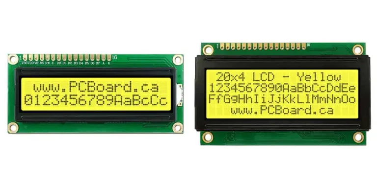
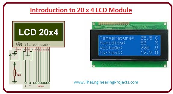
The 2x16 LCD screens have a reduced size, managing 2 rows that can contain approximately 16 characters each. The same can be said of 4x20 LCDs, where 4 rows of 20 columns or characters each are handled.
What gives us an advantage when programming them is the fact that we can use microcontrollers or development cards to be able to display the message we want on them.
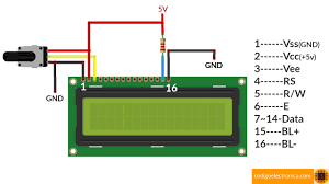
However, before programming them, we have to look at the pins that make them up:
If we look at the following image, we can see some small indentations or tracks, which represent the pins of our LCD screen.
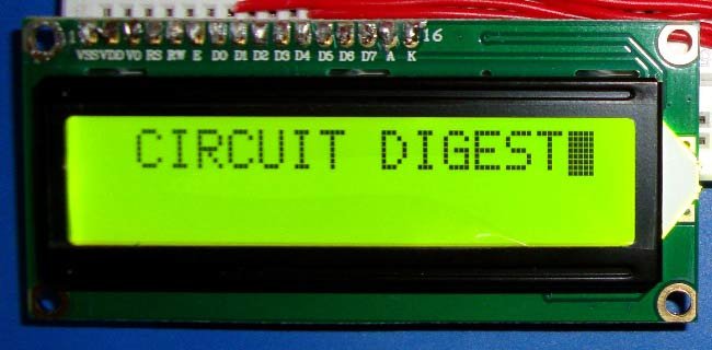
Shoutout to Circuit Digest
Here we can see that we have a total of 14 pins, each with a specific function. Explaining each one:
- VSS: Represents the ground of the LCD screen, so it must be connected to the ground of the circuit.
- VDD: This is where we connect the screen power. This should have a recommended value of 5V.
- Vo or VEE: It is the contrast control, where we can adjust the ratio for the amount of screen brightness. Typically, a potentiometer connected to the power is used to adjust this value.
- RS: This is the register select bit, which has to choose between two registers depending on whether it is high or low. If it is high, it selects the data record, which is responsible for the text strings or characters that have been entered into the program. When it is low it accesses the command register, which executes some command ordered to the screen.
- RW: This is used to tell the screen our actions regarding the records. If we are reading a record, we place the screen high; If we are writing to a register, we set this bit low.
- E: This is the enable pin, with which we can send the data that we have written with our microcontroller to the data pins if it is set high and then low (Pulse from high to low).
- Pins DB0,DB1,DB2,DB3,DB4,DB5,DB6,DB7,DB8: These pins are the so-called data pins, from which we introduce the character strings that we want to display on the screen. We can use only 4 of these pins if the screen is placed in 4-bit programming mode.
- BL+: This refers to the positive or power supply of the backlight, which will allow us to brighten the characters we write.
*BL-: This will be the backlight ground.
As for 4x20 screens, these will have the same number of pins as 2x16 LCDs, with the difference that the resolution will increase. Now, instead of having two rows of 16 columns each, we will have 4 rows of 20 columns or characters.
Shoutout to The Engineering Projects
Now that we know what each pin of the LCD screen does, we have to move on to describe what the element that makes everything possible does: The PIC microcontroller.
The PIC microcontroller
Shoutout to Microcontrollers Lab
Although I could dedicate a series of entire articles to describing what a PIC microcontroller is, we will have to settle for a simple description for this article:
A PIC microcontroller is a programmable integrated circuit, which can perform and control a large number of tasks according to how it is programmed.
Another way of seeing the PIC microcontroller is as a computer, where it has its RAM and EEPROM memories for data and the program, a CPU and peripherals. This is why, unlike primitive digital circuits, we can perform an immense number of tasks without having to resort to the extra expense of additional devices.
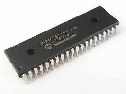
Now, in order to describe the most important pins of a PIC, we will use a simple model such as the 16F84A, of which, by looking at the following image, we can detect:
Shoutout to DataSheetMeta
- VDD (Power) and Vss (Ground) of the microcontroller.
- MCLR: It is the Master Clear or reset pin, which will allow the microcontroller to be restarted in case an error occurs. This activates on low.
- OSC1 and OSC2: These are the pins to which we connect the crystal oscillator if using it. (They determine the operating frequency of the PIC).
- T0CK1: Pin for Timer 0.
- RA0 to RA7 and RB0 to RB7 - These are the digital input/output pins, which we will use to send or receive data in the PIC according to whether we program them as input or output.
Now, to make a PIC work properly, we will always require:
- A power supply (5V)
- A button and resistor for the MCLR pin.
- If you plan to use high oscillator frequencies, an oscillation crystal.
*Whatever the program requires
Thus, knowing this, we can move on to observe the physical connections of this microcontroller.
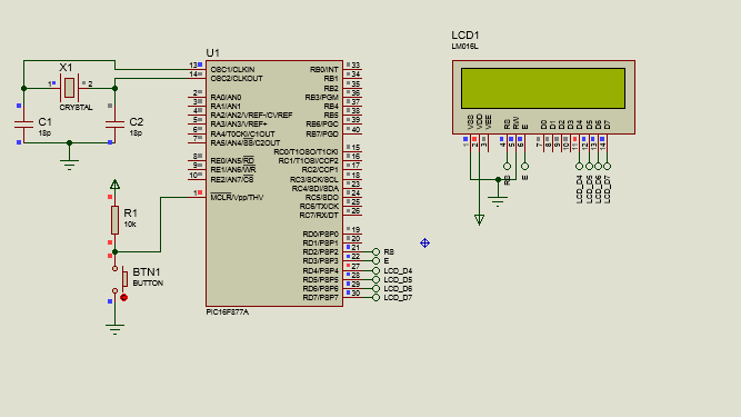
Connecting the PIC to the LCD
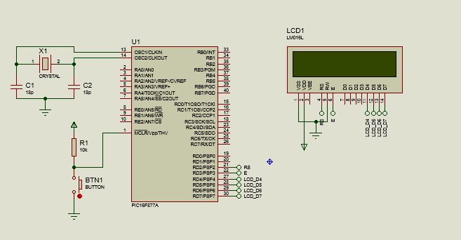
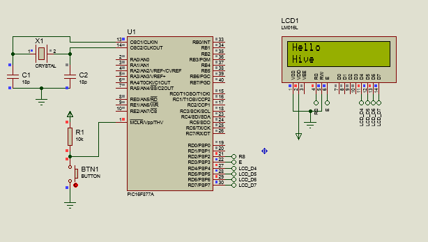
As we can see in the figure, we see that the PIC is connected by OSC1 and OSC2 to a 20MHz crystal oscillator, this is to work with a higher frequency and therefore a shorter time between operation. Additionally, we see that we have a pull-up resistor (This is a resistor connected to the power supply) and a grounded button connected to MCLR. This is so that the Reset effect occurs in the PIC when we press the button.
Additionally, we can notice that the input/output pins will be connected to the 2x16 LCD. In this case we take the pins RD2 to RD7 (For the PIC16f877 we have 4 input/output ports, unlike the 2 of the 16f84).
Since the data will go from the PIC to the LCD, we will know that these pins will be configured as outputs.
Now, looking at the 2x16 LCD, we notice that VDD is connected to power and VSS is connected to ground just like RW, this is because we only want to write to the LCD registers to display the data.
RS is connected to RD2, which will be set high most of the time since we will only be entering data into the data register.
E is connected to RD3, through which the PIC will emit a short pulse to indicate that the LCD data is being updated.
And finally the data bits, which connect to RD4,RD5,RD6 and RD7, which are the data pins. Since we are using programming mode with 4 bits, we only use these.
We notice that the backlight pins (BL- and BL+) are omitted due to the fact that we have a simulation. If there is a physical connection, BL+ is connected to the power supply and BL- to ground. Additionally, the Vee (Contrast) would be connected to the output of a potentiometer in conjunction with the output.
Now that we know how to establish the connections in our PIC, we would like to know how the code works to make this possible.
Establishing the program
In this case, we reiterate that a high-level programming language is used to make the process more understandable for beginners. In this case we will use C with the CCS C Compiler programming environment. To create a source file for our code, in this we go to file and select new>source file to create it.
Once we are here, the first thing we will have to do is go to the compile section and set the model of our microcontroller to target (In this case the PIC16F877A).
Now starting to program, the first thing we will do is establish the configuration of our PIC using the following instructions:
#include <16f877a.h>
#fuses HS,NOWDT,NOPUT,BROWNOUT,NOPROTECT,NOLVP
#use delay(clock=20M)
#use standard_io(D)
What the #include instruction does is that it allows us to introduce libraries that are found in the drivers folder of our CCS C. In this case we introduce the 16f877a.h library, which will be the library of our PIC.
Additionally, we note that with fuses we determine the fuses or configuration pins of our PIC that we will use. In this case we use HS since we use a crystal with more than 4MHz, NOWDT since we do not want a Watch Dog Timer, which resets the program from time to time.
Likewise, we use NOPUT to indicate the No Power Up Timer, with which we mention that we do not want a timer that waits for the voltage to stabilize before starting the program (However, it is highly recommended for physical projects).
- Thus, we use Brownout, NOPROTECT to avoid copy protection mode and NOLVP since we will not use the low voltage programming mode.
The #use delay corresponds to the speed or frequency of the oscillator that we will use. Since we will use an external 20 MHZ crystal, clock=20M is set as a parameter.
Finally, with the #use standard_io(D), we resort to an instruction to determine the state of the input/output pins of the bit, where in this case, we will have to configure them later to use them.
Later, to configure the pins as required by the 16x2 LCD library, we will have to use the following:
#define LCD_DB4 PIN_D4
#define LCD_DB5 PIN_D5
#define LCD_DB6 PIN_D6
#define LCD_DB7 PIN_D7
#define LCD_RS PIN_D2
#define LCD_E PIN_D3
#include <LCD_16X2.c>
Note: The Names of LCD_DB4, LCD_DB5, etc... must be maintained since they are registered in the library in this way, which means that when changing them the library does not work.
With the define instruction, we will assign a new name to the pins of port D, where in the case of pin 4, this would be called LCD_DB4, a name by which the microcontroller would recognize it. This is repeated for each pin that we are going to use.
These pins will be the ones that will be connected to the LCD, as long as a library is introduced (Hence the include command), LCD_16X2.C, which is a library for managing 16x2 LCD displays.
If you don't know how to install a library, this is really simple. You just have to access the following link to download the library that we will use in this case.
Once it is downloaded, we go to the installation folder of our IDE (In this case the PIC C Compiler) and look for the Drivers folder:
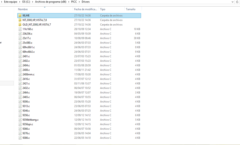
Once we are here, we will only have to move the library file here and we can use it without any problem.
Now, to manage this library and use it in our program, we must take into account the following commands:
lcd_init(), which starts the LCD screen for us to use.
lcd_gotoxy(a,b), Takes us to a specific position on the LCD screen, where a will be the column number and b the row number (Maximum 2 for LCD_16x2)
lcd_putc(), which allows us to write the message we want, as long as it is in the memory of the LCD screen microcontroller.
lcd_clear(), with which we clear the content of the LCD screen.
CGRAM_position(). The LCD memory has memory spaces known as CGRAM, which will be where we will store personalized characters that we store in our program. With CGRAM_position we go to a specific position of this CGRAM to save a created character.
CGRAM_create_char(). This is a command that will allow us to create the custom character and save it in the memory location mentioned above. This character will be created in the form of an array, which we will introduce as a parameter.
CGRAM_putc(). With this, we can display on the LCD screen the character that we save in the LCD when specifying its CGRAM position.
For the purposes of this article, we will use only the first four instructions. Looking at the body of the program:
void main()
{
    lcd_init();

    while(TRUE)
    {
       lcd_gotoxy(1,1);
       lcd_putc("Hello");
       delay_ms(500);

       lcd_gotoxy(1,2);
       lcd_putc("Hive");
       delay_ms(1000);

       lcd_clear();
       delay_ms(200);
       //TODO: User Code
    }

}
The first thing we will do is create a function called main(), where we will store the execution code. Then, before the while loop, which will run infinitely (Hence the while(true)) we will use lcd_init() to tell the LCD to start.
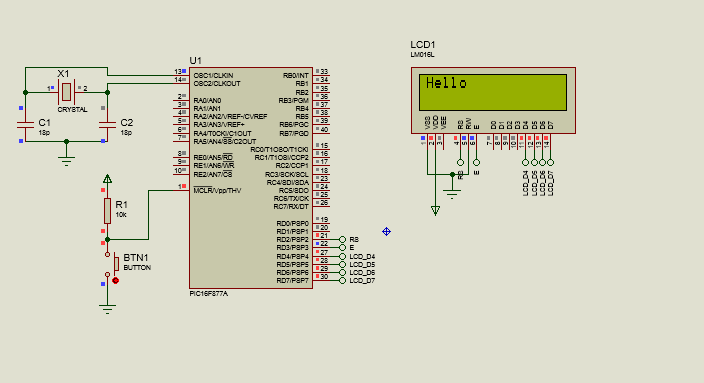
Within the loop, the first thing we will do is go to the first row in the first column or character (lcd_gotoxy(1,1)), and we will place the "Hello" message with lcd_putc(). Subsequently, we use a small delay of 0.5s (delay_ms).
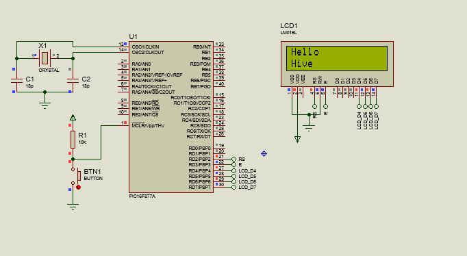
Later, we repeat the same process, only now we go to the second row and write "Hive", a message that will last 1 second (1000ms).
Finally, what we do is clean the screen and place a 200ms delay before everything repeats itself. The program would look like this:
#include <16f877a.h>
#fuses HS, NOWDT, NOPROTECT, NOPUT, NOLVP, BROWNOUT
#use delay(clock=20M)
#use standard_io(D)

#define LCD_DB4 PIN_D4
#define LCD_DB5 PIN_D5
#define LCD_DB6 PIN_D6
#define LCD_DB7 PIN_D7
#define LCD_RS PIN_D2
#define LCD_E PIN_D3
#include <LCD_16X2.c>


void main()
{
    lcd_init();

    while(TRUE)
    {
       lcd_gotoxy(1,1);
       lcd_putc("Hello");
       delay_ms(500);

       lcd_gotoxy(1,2);
       lcd_putc("Hive");
       delay_ms(1000);

       lcd_clear();
       delay_ms(200);
       //TODO: User Code
    }
}
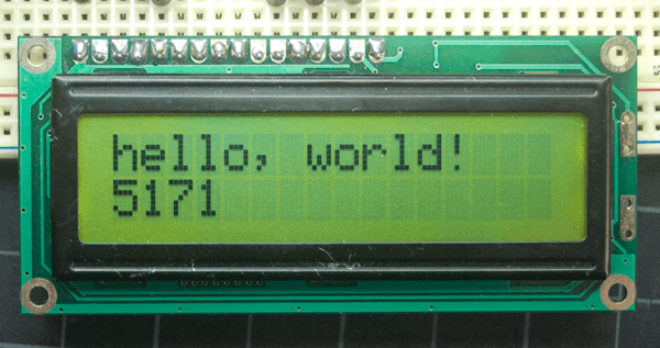
And so, we would have our program that, when executed, would look like this:
Managing devices such as displays is not complex, we just need to know how they are connected and some basic programming in C to obtain results like the ones we have seen.
In addition to this, LCDs are frequently used in conjunction with other peripherals, such as sensors, keyboards and many other devices, which make the practical applications of PICs practically unlimited.
I encourage you to put the knowledge you have acquired into practice and make suggestions if you see something interesting. Thus:
Used Programs
- Proteus 8 Professional.
- CCS C Compiler.

Entrando al mundo de los PIC
Shoutout to Arduino
En este artículo encontrarás:
- Introducción
- ¿Qué es un LCD?
- Pantallas LCD 2x16 y 4x20
- El microcontrolador PIC
- Estableciendo el Programa
Un saludo a toda la comunidad de Hive.
Hasta ahora, he hablado de un montón de temas concerniendo la ingeniería, desde la programación y la orientación espacial hasta la composición de los PIC en mis primeros artículos. Sin embargo, nunca hemos mezclado el hardware y el software para hablar de proyectos con microcontroladores.
Es por esto, que en el presente, se hará una introducción a la programación de los PIC, esto por medio de la creación de un programa que nos permita escribir cadenas de caracteres en un LCD.
En este caso, para facilitar la visualización de los efectos, usaremos Proteus y un entorno de programación de alto nivel, que es PIC C Compiler. En un futuro veremos la programación de bajo nivel con Assembler, sin embargo, solo queda esperar.
De esta forma, si quieres saber como manejar un display LCD con un microcontrolador PIC, solo tienes que seguir leyendo.
¿Qué es un LCD?
Shoutout to Codigo Electronica
Una pantalla LCD o pantalla de cristal líquido, es un dispositivo que nos permite representar por medio de píxeles en frente de una fuente de luz o pantalla reflectora cualquier imagen.
Las pantallas LCD de las que escuchamos con mayor frecuencia son las que usamos de manera cotidiana: La pantalla de nuestros televisores y ordenadores.
Este tipo de pantallas LCD representan magnitudes elevadas de pixeles, donde en un monitor con soporte de 1080p Full HD, se tendrá una resolución 1920x1080, lo que representa un total de 2073600 pixeles.
Ahora bien, ¿Qué representa esta resolución?:
- El primer número (antes de la x) representa las dimensiones horizontales. Es decir, la cantidad de filas de pixeles en tu pantalla.
- El segundo número (después de la x) son las dimensiones verticales, que son la cantidad de columnas de pixeles que tendrá la pantalla.
La razón por la que la LCD ha gozado de gran popularidad es por el hecho de su bajo consumo de energía, donde los televisores LCD consumen entre 30 y 80W frente a los 152W consumidos por un televisor de rayo catódico (CRT) de 28 pulgadas.
Ahora bien, debido al hecho de que el manejo de grandes cantidades de filas y columnas pixeles puede ser algo complicado, comenzaremos con algo sencillo que podemos manejar: una pantalla LCD de 2x16 y una de 4x20 para trabajo con microcontroladores.
Veamos como esta funciona:
Pantallas LCD 2x16 y 4x20
Shoutout to Leds, Arduino, IoT and Electronics
Las pantallas LCD de 2x16 tienen un tamaño reducido, manejando 2 filas que pueden contener aproximadamente una cantidad de 16 caracteres cada una. Lo mismo se puede decir de las LCD 4x20, donde se manejan 4 filas de 20 columnas o caracteres cada una.
Lo que nos supone una ventaja a la hora de programarlas es el hecho de que podemos usar microcontroladores o tarjetas de desarrollo para poder mostrar el mensaje que queramos en estas.
Sin embargo, antes de pasar a programarlas, tenemos que observar los pines que las componen:
Si observamos la siguiente imagen, podremos ver unas pequeñas hendiduras o pistas, que representan los pines de nuestra pantalla LCD.
Shoutout to Circuit Digest
Aquí podemos ver que tenemos un total de 14 pines, cada uno con una función específica. Explicando cada uno:
- VSS: Representa la tierra de la pantalla LCD, por lo que debe ser conectada a la tierra del circuito.
- VDD: Es aquí donde conectamos la alimentación de la pantalla. Esta debe tener un valor recomendado de 5V.
- Vo o VEE: Es el control de contraste, donde podemos ajustar la relación para la cantidad de brillo de la pantalla. Por lo general, se usa un potenciómetro conectado a la alimentación para ajustar este valor.
- RS: Este es el bit de selección del registro, el cual tiene que escoger entre dos registros dependiendo de si está en alto o en bajo. Si está en alto, selecciona el registro de datos, encargado de las cadenas de texto o caracteres que se hayan introducido al programa. Cuando está en bajo accede al registro de comandos, que ejecuta algún comando ordenado a la pantalla.
- RW: Este se usa para indicarle a la pantalla nuestras acciones con respecto a los registros. Si estamos leyendo un registro, colocamos la pantalla en alto; Si estamos escribiendo en un registro, colocamos este bit en bajo.
- E: Este es el pin de enable, con el cual podemos enviar los datos que hayamos escrito con nuestro microcontrolador a los pines de datos si este se coloca en alto y luego en bajo (Pulso de alto a bajo).
- Pines DB0,DB1,DB2,DB3,DB4,DB5,DB6,DB7,DB8: Estos pines son los llamados pines de datos, desde los cuales introducimos las cadenas de caracteres que queremos mostrar en la pantalla. Podemos usar solo 4 de estos pines si se coloca la pantalla en modo de programación con 4 bits.
- BL+: Este se refiere al positivo o la alimentación de la luz de fondo, la cual permitirá dar brillo a los caracteres que escribamos.
- BL-: Esta será la tierra de la luz de fondo.
En cuanto a las pantallas de 4x20, estas tendrán el mismo número de pines que las LCD de 2x16, con la diferencia de que la resolución aumentará. Ahora, en vez de tener dos filas de 16 columnas cada una, tendremos 4 filas de 20 columnas o caracteres.
Shoutout to The Engineering Projects
Ahora que sabemos que hace cada pin de la pantalla LCD, tenemos que pasar a describir que hace el elemento que hace todo posible: El microcontrolador PIC.
El microcontrolador PIC
Shoutout to Microcontrollers Lab
Aunque podría dedicar una serie de artículos completos a describir que es un microcontrolador PIC, tendremos que conformarnos con una descripción simple para este artículo:
Un microcontrolador PIC es un circuito integrado programable, que puede realizar y controlar una gran cantidad de tareas de acuerdo a como se programe.
Otra forma de ver al microcontrolador PIC es como una computadora, donde este tiene sus memorias RAM y EEPROM para datos y el programa, una CPU y periféricos. Es por esto, que a diferencia de circuitos digitales primitivos, podemos realizar una cantidad inmensa de tareas sin tener que recurrir al gasto extra de dispositivos adicionales.
Ahora, en orden de describir los pines más importantes de un PIC, usaremos un modelo sencillo como lo es el 16F84A, del cual, al observar la siguiente imagen, podemos detectar:
Shoutout to DataSheetMeta
- VDD (Alimentación) y Vss (Tierra) del microcontrolador.
- MCLR: Es el pin de Master Clear o reset, el cual permitirá reiniciar el microcontrolador en caso de que ocurra algún error. Este se activa en bajo.
- OSC1 y OSC2: Estos son los pines a los cuales conectamos el cristal oscilador en caso de usarlo. (Determinan la frecuencia de operación del PIC).
- T0CK1: Pin para el Timer 0.
- RA0 a RA7 y RB0 a RB7 - Estos son los pines de entrada/salida digital, los cuales usaremos para enviar o recibir datos en el PIC de acuerdo a si las programamos como entrada o salida.
Ahora bien, Para hacer que un PIC funcione de manera adecuada, siempre requeriremos:
- Una fuente de alimentación (5V)
- Un botón y resistor para el pin de MCLR.
- Si se planea usar frecuencias altas de oscilador, un cristal de oscilación.
- Lo que el programa requiera
Así, sabiendo esto, podemos pasar a observar las conexiones físicas de este microcontrolador.
Conectando el PIC a la LCD
Como podemos observar en la figura, vemos que el PIC se encuentra conectado por OSC1 y OSC2 a un cristal oscilador de 20MHz, esto es para trabajar con una frecuencia más alta y por lo tanto un tiempo menor entre operación. Además, vemos que se tiene un resistor pull-up (Esto es un resistor conectado a la alimentación) y un botón conectado a tierra conectado a MCLR. esto es para que se produzca el efecto de Reset en el PIC cuando presionemos el botón.
Además, podemos notar que los pines de entrada/salida se encontrarán conectados al LCD 2x16. En este caso tomamos los pines RD2 a RD7 (Para el PIC16f877 tenemos 4 puertos de entrada/salida, a diferencia de los 2 del 16f84).
Ya que los datos irán desde el PIC hasta el LCD, sabremos que estos pines estarán configurados como salidas.
Ahora, poniendo el ojo en el LCD 2x16, notamos que VDD va conectado a la alimentación y VSS va a tierra al igual que RW, esto debido a que solo queremos escribir en los registros del LCD para mostrar los datos.
RS se encuentra conectado a RD2, el cual se colocará en alto la mayor parte del tiempo ya que solo introduciremos datos al registro de datos.
E se encuentra conectado a RD3, por medio del cual el PIC emitirá un pulso breve para indicar que se están actualizando los datos del LCD.
Y finalmente los bits de datos, los cuales se conectan a RD4,RD5,RD6 y RD7, que son los pines de datos. Ya que estamos usando el modo de programación con 4 bits, solo usamos estos.
Notamos que se omiten los pines de iluminación de fondo (BL- y BL+) debido al hecho de que se tiene una simulación. En caso de que se tenga una conexión física, BL+ se conecta a la alimentacion y BL- a tierra. Además, el Vee (Contraste) se conectaría a la salida de un potenciómetro en conjunción con la salida.
Ahora que sabemos como establecer las conexiones en nuestro PIC, nos restaría conocer como funciona el código para hacer esto posible.
Estableciendo el programa
En este caso, reiteramos que se usa un lenguaje de programación de alto nivel para hacer el proceso más entendible para principiantes. En este caso usaremos C con el entorno de programación CCS C Compiler. Para crear un archivo fuente para nuestro código, en este nos dirigimos a file y seleccionamos new>source file para crearlo.
Una vez que nos encontramos aquí, lo primero que tendremos que tendremos que hacer es dirigirnos a la sección de compile y establecer en target el modelo de nuestro microcontrolador (En este caso el PIC16F877A).
Ahora comenzando a programar, lo primero que haremos será establecer la configuración de nuestro PIC por medio de las siguientes instrucciones:
#include <16f877a.h>
#fuses HS,NOWDT,NOPUT,BROWNOUT,NOPROTECT,NOLVP
#use delay(clock=20M)
#use standard_io(D)
Lo que hace la instrucción #include, es que nos permite introducir librerías que se encuentren en la carpeta drivers de nuestro CCS C. En este caso introducimos la librería 16f877a.h, que será la librería de nuestro PIC.
Además, notamos que con fuses determinamos los fusibles o pines de configuración de nuestro PIC que usaremos. En este caso usamos HS ya que usamos un cristal de más de 4MHz, NOWDT ya que no queremos un Watch Dog Timer, que resetea el programa cada cierto tiempo.
De igual forma, usamos NOPUT para indicar el No Power Up Timer, con el que mencionamos que no queremos un timer que espera que se estabilice el voltaje antes de empezar el programa (Sin embargo es bastante recomendado para proyectos físicos).
- Así, utilizamos Brownout, NOPROTECT para no colocar el modo de protección contra copiado y NOLVP ya que no usaremos el modo de programación en bajo voltaje.
El #use delay corresponde a la velocidad o frecuencia del oscilador que usaremos. Ya que usaremos un cristal externo de 20 MHZ, se coloca como parámetro el clock=20M.
Finalmente, con el #use standard_io(D), recurrimos a una instrucción para determinar el estado de los pines de entrada/salida del bit, donde en este caso, tendremos que configurarlos posteriormente para usarlos.
Posteriormente, para configurar los pines según lo requerido por la librería del LCD de 16x2, tendremos que usar lo siguiente:
#define LCD_DB4 PIN_D4
#define LCD_DB5 PIN_D5
#define LCD_DB6 PIN_D6
#define LCD_DB7 PIN_D7
#define LCD_RS PIN_D2
#define LCD_E PIN_D3
#include <LCD_16X2.c>
Nota: Los Nombres de LCD_DB4, LCD_DB5, etc... deben de mantenerse ya que en la librería están registrados de esta manera, lo que hace que al cambiarlos no funcione la librería.
Con la instrucción define, le asignaremos un nuevo nombre a los pines del puerto D, donde en el caso del pin 4, este pasaría a llamarse LCD_DB4, nombre por el que lo reconocería el microcontrolador. Esto se repite para cada pin que vamos a usar.
Estos pines serán los que se conectarán al LCD, siempre y cuando se introduzca una librería (De aquí el comando include), la LCD_16X2.C, que es una librería para el manejo de displays LCD de 16x2.
Si no sabes como instalar una librería, esto es realmente sencillo. Solo tienes que acceder al siguiente enlace para descargar la librería que usaremos en este caso.
Una vez que esté descargada, nos dirigimos a la carpeta de instalación de nuestro IDE (En este caso el PIC C Compiler) y buscamos la carpeta de Drivers:
Una vez estemos aquí, solo tendremos que mover el archivo de la librería hasta aquí y la podremos usar sin ningún problema.
Ahora bien, para manejar esta librería y usarla en nuestro programa, debemos de tomar en cuenta los siguientes comandos:
lcd_init(), que inicia la pantalla LCD para que la usemos.
lcd_gotoxy(a,b), Nos lleva a una posición específica de la pantalla LCD, donde a será el número de columna y b el número de fila (Máximo 2 para el LCD_16x2)
lcd_putc(), que nos permite escribir el mensaje que queramos, siempre y cuando se encuentre en la memoria del microcontrolador de la pantalla LCD.
lcd_clear(), con el que limpiamos el contenido de la pantalla LCD.
CGRAM_position(). La memoria de la LCD posee unos espacios de memoria conocidos como CGRAM, que será donde almacenaremos caracteres personalizados que almacenemos en nuestro programa. Con CGRAM_position nos dirigimos a una posición específica de esta CGRAM para guardar un caracter creado.
CGRAM_create_char(). Este es un comando que nos permitirá crear el caracter personalizado y guardarlo en la posición de memoria mencionada anteriormente. Este caracter será creado en forma de un arreglo, el cual introduciremos como parámetro.
CGRAM_putc(). Con este, podremos mostrar en la pantalla LCD el caracter que guardemos en la LCD al especificar su posición CGRAM.
Para efectos de este artículo, usaremos solo las primeras cuatro instrucciones. Observando el cuerpo del programa:
void main()
{
   lcd_init();

   while(TRUE)
   {
      lcd_gotoxy(1,1);
      lcd_putc("Hello");
      delay_ms(500);

      lcd_gotoxy(1,2);
      lcd_putc("Hive");
      delay_ms(1000);

      lcd_clear();
      delay_ms(200);
      //TODO: User Code
   }

}
Lo primero que haremos es crear una función llamada main(), donde almacenaremos el código de ejecución. Luego, antes del ciclo while, el cual se ejecutará infinitamente (Por eso el while(true)) usaremos lcd_init() para indicar que se inicie el LCD.
Dentro del ciclo, lo primero que haremos será dirigirnos a la primera fila en la primera columna o caracter (lcd_gotoxy(1,1)), y colocaremos el mensaje de "Hello" con lcd_putc(). Posteriormente, usamos un pequeño retraso de 0.5s (delay_ms).
Posteriormente, repetimos el mismo proceso, solo que ahora vamos a la segunda fila y escribimos "Hive", mensaje que durará 1 segundo (1000ms).
Finalmente, lo que hacemos es limpiar la pantalla y colocar un retardo de 200ms antes de que todo vuelva a repetirse. El programa se vería de la siguiente forma:
#include <16f877a.h>
#fuses HS, NOWDT, NOPROTECT, NOPUT, NOLVP, BROWNOUT
#use delay(clock=20M)
#use standard_io(D)

#define LCD_DB4 PIN_D4
#define LCD_DB5 PIN_D5
#define LCD_DB6 PIN_D6
#define LCD_DB7 PIN_D7
#define LCD_RS PIN_D2
#define LCD_E PIN_D3
#include <LCD_16X2.c>


void main()
{
   lcd_init();

   while(TRUE)
   {
      lcd_gotoxy(1,1);
      lcd_putc("Hello");
      delay_ms(500);

      lcd_gotoxy(1,2);
      lcd_putc("Hive");
      delay_ms(1000);

      lcd_clear();
      delay_ms(200);
      //TODO: User Code
   }
}
Y así, tendríamos nuestro programa que al ejecutarse, se vería de la siguiente manera:
El manejo de dispositivos como displays no es algo complejo, solo debemos de conocer la forma en que son conectados y algo de programación básica en C para obtener resultados como los que hemos visto.
Además de esto, los LCDs son usados con gran frecuencia en conjunción con otros periféricos, como lo son sensores, teclados y muchos otros dispositivos, los que hacen que las aplicaciones prácticas de los PICs sean practicamente ilimitadas.
Te animo a poner en práctica el conocimiento adquirido y a hacer sugerencias si ves algo interesante. De esta forma:
Programas Usados
- Proteus 8 Professional.
- CCS C Compiler.
Thanks for your contribution to the STEMsocial community. Feel free to join us on discord to get to know the rest of us!
Please consider delegating to the @stemsocial account (85% of the curation rewards are returned).
You may also include @stemsocial as a beneficiary of the rewards of this post to get a stronger support.
Literally nostalgic to read about PIC after my first projects nearly 20 years ago :)
Great to know that you enjoyed It!
I was thinking of making the series about Arduino Boards with the Atmel Microcontrollers, but I finally decided for PIC. The hardest part was choosing between using C language or Assembler.