Interrupts with Timer1 | Interrupciones con el Timer1 - Microcontrollers #12 [EN/ES]
Interrupts with Timer1
Shoutout to DeepBlueMbedded

In this article you'll find:
- Introduction
- The Timer1
- Connections
- Establishing the Code
- Running the Program
Greetings everyone and welcome to another edition of microcontrollers!
In the previous article, we talked about the internal interruptions that are carried out with timers, specifically timer0, checking their precision with respect to the times established in the main program.
Now, we will follow a fairly similar line, where instead of using Timer0, we will use Timer1.
So if you want to expand your knowledge about timers and create projects with them, you just have to keep reading.
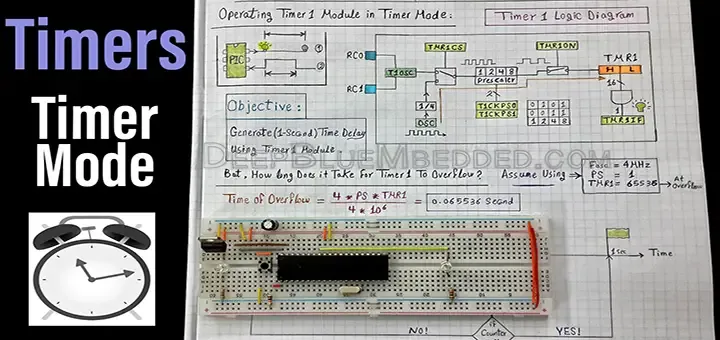
Timer1
Shoutout to skills.microchip.com
In the previous edition 11-en) we explain in detail the timers and how they work, using Timer0 as an example.
Timer1 is actually similar to timer0, with a couple of exceptions:
- Instead of having an 8-bit value and counting up to 256 clock pulses, Timer1 has 16 bits, so it can count up to 65536 clock pulses.
- The Timer0 prescaler had 9 types of prescaler ranging from 1 to 256. Timer1 allows us to choose between 4 prescaler values, which are 1,2,4 and 8.
This means that when we need longer times for interruptions to be generated (having a maximum of 104ms), we will use this Timer.
Now, if we remember that Timer0 had an equation that allows us to calculate the load value that we will assign to Timer0, which was:
TMR0 = 256 -  T * Fosc
            -------------
            4 * Prescaler
Where T was the period of time we want to wait for the interruption to occur and Fosc the frequency of the microcontroller oscillator.
For Timer1, the equation only presents one change. Now, instead of using 256, we will use 65536 since the number of bits is greater by 8. Thus, to calculate the TMR1 load:
TMR1 = 65536 -  T * Fosc
              ------------
               4*Prescaler
In this way, if we wanted the 1ms of the example in the previous post using a prescaler of 8, we would have:
TMR1 = 65536 - 0.001 * 20,000,000
              ---------------------
                     4*8

TMR1 = 64911
And in this way, we now know how to calculate the value of Timer1 that we require for a given time.
With this in mind, we can see the connections of our program.
Connections
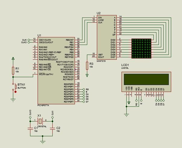
If we look at the image, we can confirm that we will use two external peripherals. One of these will be the MAX7219, which will allow us to display messages on the 8x8 LED matrix using only 3 pins and the 16x2 LCD screen.
The DATA, LOAD and CLK pins of the MAX7219 will be connected to the RB0, RB1 and RB2 pins respectively, while the LCD data pins (DB4,DB5,DB6,DB7) will be connected to RD4,RD5,RD6 and RD7, placing RS and E with RD2 and RD3 at the same time.
Since the main function of the program will be a comparison, a counter will be incremented from 0 to 9 on the LCD screen, in the same way as it will be on the LED matrix, to verify the accuracy of Timer1.
Now that we know about the connections, we can move on to the code.
Setting the code
Before starting to write the code of our program, we must take a look at the connections that make it possible for the value calculated in the first section to be entered into Timer1. For this, we will again use enable_interrupts and the interrupt function labeling.
Changing with respect to timer0 we have the use of setup_timer1, where we will continue to have two parameters, one for the mode and another for the prescaler.
For the prescaler, depending on the value, we will use:
- T1_DIV_BY_1
- T1_DIV_BY_2
- T1_DIV_BY_4
- T1_DIV_BY_8
And for the mode:
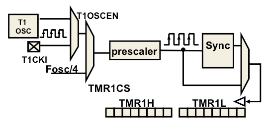
T1_INTERNAL; Which will be timer1 used as a timer, that is, it will use the microcontroller clock as the source of the pulses.
T1_EXTERNAL; Here, a pulse generator or button connected to the RC0 pin is used as a source of the clock pulses, which would be used as a counter.
T1_EXTERNAL_SYNC; Likewise, the pulse introduced to RC0 would be used as the source of the pulses.
T1_CLK_OUT; Here the RC1 PIN would be used as a clock output.
Thus, if we wanted to configure timer1 in timer mode with prescaler 8, we would use the instruction set_timer_1(T1_INTERNAL | T1_DIV_BY_8)
Now, for our program, we want the counter increment for the LED array to be every 100ms, so we start calculating:
T = 100ms (0.1s)

TMR1 = 65536 - T * Fosc
              ----------
             4 * Prescaler

TMR1 = 65536 - 0.1 * 20,000,000
              ------------------
                    4*8

TMR1 = 3036
So now we know the load value for TMR1 and we can move on to the program demonstration. For the first lines of code:
#include <16f877a.h>
#fuses HS, NOWDT, NOPROTECT, NOPUT, NOLVP, BROWNOUT
#use delay(clock=20M)
#use standard_io(D)
#use standard_io(B)

#define LCD_DB4 PIN_D4
#define LCD_DB5 PIN_D5
#define LCD_DB6 PIN_D6
#define LCD_DB7 PIN_D7
#define LCD_RS PIN_D2
#define LCD_E PIN_D3
#include <LCD_16X2.c>

#define DATA PIN_B0
#define LOAD PIN_B1
#define CLK PIN_B2
#include <MAX7219.c>


unsigned char numbers[10] = {'0','1','2','3','4','5','6','7','8','9'};
int counter = 0;
int counter2 = 0;
Here we can see the standard configuration that we have been studying in previous articles. For the LCD display, we define the port D pins to match the library names LCD_16x2.c and the same for the MAX7219.
If you want to know how this is done, you just have to read the articles on LCD Screens and LED Matrices.
Next, we define the array of characters that we will use to display in the matrix, going with the values from 0 to 9. Subsequently, we create counter and counter2, one to be the counter of the main program, that is, the value that will be displayed on the screen LCD and another to allow us to scroll through the matrix arrangement.
Then for the interrupt function:
#INT_TIMER1
void timer1_interrupt()
{
    counter2++;
    display_char(numbers[counter2]);

    if(count2 > 9)
    {
       counter2 = 0;
       display_char(numbers[counter2]);
    }
    set_timer1(3036);
}
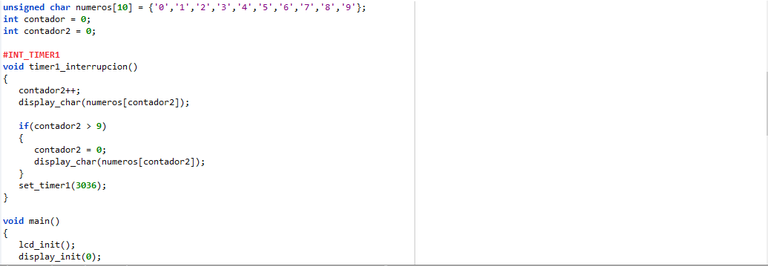
Here, the label to define the function will be INT_TIMER1 and within this, we will make counter2 increment, so that it shows us the content of the array with characters 1 to 10, taking elements 0 to 9 with display_char.
However, if it exceeds 9, the counter will reset, which is why we use the conditional. Once passed, the counter returns to 0 and is shown on the screen.
We must always remember to set the timer with the load value, this to determine the time it takes to execute the next interruption.
In the main program:
void main()
{
    lcd_init();
    display_init(0);
    seg_putc(1);
    setup_timer_1(T1_INTERNAL | T1_DIV_BY_8);
    enable_interrupts(INT_TIMER1);
    enable_interrupts(GLOBAL);
    set_timer1(3036);


    while(TRUE)
    {
      lcd_gotoxy(1,1);
      lcd_putc("Number: ");
      for(int counter = 0; counter < 9; counter++)
      {
          lcd_gotoxy(1,2);
          printf(lcd_putc, "%u", counter);
          delay_ms(100);
      }
    }
}
We can see that at the beginning of the void main, part of the function that we use to configure the main program, we start the lcd screen (lcd_init()) and the display (display_init(0): Common Cathode; seg_putc(1): It will only be used an LED matrix).
Then, as is customary for timer interrupts, we use setup_timer_1 to determine what will be used as a timer and with a Prescaler of 8, followed by activating the interrupts with Timer1 (enable_interrupts(TIMER_1)), in addition to the global ones.
Finally, in order for the first interruption to be fulfilled within the scheduled 100ms, we use set_timer1 with the load value (3036).
And for the cycle, we will write in the first row "Number: " and then increment the first counter with a for cycle up to 9 and displaying its value in the first column of row 2 with a delay of 100 ms.
If we put all this together, we will have:
#include <16f877a.h>
#fuses HS, NOWDT, NOPROTECT, NOPUT, NOLVP, BROWNOUT
#use delay(clock=20M)
#use standard_io(D)
#use standard_io(B)

#define LCD_DB4 PIN_D4
#define LCD_DB5 PIN_D5
#define LCD_DB6 PIN_D6
#define LCD_DB7 PIN_D7
#define LCD_RS PIN_D2
#define LCD_E PIN_D3
#include <LCD_16X2.c>

#define DATA PIN_B0
#define LOAD PIN_B1
#define CLK PIN_B2
#include <MAX7219.c>


unsigned char numbers[10] = {'0','1','2','3','4','5','6','7','8','9'};
int counter = 0;
int counter2 = 0;

#INT_TIMER1
void timer1_interrupt()
{
    counter2++;
    display_char(numbers[counter2]);

    if(count2 > 9)
    {
       counter2 = 0;
       display_char(numbers[counter2]);
    }
    set_timer1(3036);
}

void main()
{
    lcd_init();
    display_init(0);
    seg_putc(1);
    setup_timer_1(T1_INTERNAL | T1_DIV_BY_8);
    enable_interrupts(INT_TIMER1);
    enable_interrupts(GLOBAL);
    set_timer1(3036);


    while(TRUE)
    {
      lcd_gotoxy(1,1);
      lcd_putc("Number: ");
      for(int counter = 0; counter < 9; counter++)
      {
          lcd_gotoxy(1,2);
          printf(lcd_putc, "%u", counter);
          delay_ms(100);
      }
    }
}
Executing the Program
Once the correct connections have been made and compiled, we can run the program, where we will see:
Here, we can notice that both the sequence from 0 to 9 in the matrix and in that of the LED are made in really similar increments, even if not perfectly exact.
And in this way, you will be able to notice that the use of Timer1 is another infallible tool.
I hope this article has helped you understand how Timers work.
Since timers are only a small part of external interruptions, in later articles we will see what other internal PIC peripherals we can use to create impressive effects.
However, we have yet to see Timer2, used to generate frequencies in conjunction with CCP modules. So, if you don't want to miss the interruptions, keep reading.
Having said that:

Interrupciones con el Timer1
Shoutout to DeepBlueMbedded
En este artículo encontrarás:
- Introducción
- El Timer1
- Conexiones
- Estableciendo el Código
- Ejecutando el Programa
¡Un saludo a todos y bienvenidos a otra edición de microcontroladores!
En el artículo previo, hablamos sobre las interrupciones internas que se llevan a cabo con timers, específicamente el timer0, comprobando su precisión respecto a los tiempos establecidos en el programa principal.
Ahora, seguiremos una línea bastante similar, donde en vez de usar el Timer0, emplearemos el Timer1.
Así si quieres ampliar tu conocimiento sobre los timers y crear proyectos con estos, solo tienes que seguir leyendo.
El Timer1
Shoutout to skills.microchip.com
En la edición previa explicamos a detalle los timers y como funcionan, colocando como ejemplo el Timer0.
El timer1 es realmente similar al timer0, con un par de excepciones:
- En vez de tener un valor de 8 bits y contar hasta 256 pulsos de reloj, el Timer1 tiene 16 bits, con lo que puede contar hasta 65536 pulsos de reloj.
- El prescaler del Timer0 tenía 9 tipos de prescaler que iban del 1 al 256. El timer1 nos permite escoger entre 4 valores de prescaler, que son 1,2,4 y 8.
Esto hace que cuando necesitemos tiempos mayores para que se generen las interrupciones (Teniendo como máximo 104ms), emplearemos este Timer.
Ahora bien, si recordamos que el Timer0 tenía una ecuación que nos permite calcular el valor de carga que asignaremos al Timer0, la cual era:
TMR0 = 256 - T * Fosc
             ---------
              4 * Prescaler
Donde T era el período de tiempo que queremos esperar para que se produzca la interrupción y Fosc la frecuencia del oscilador del microcontrolador.
Para el Timer1, la ecuación solo presenta un cambio. Ahora, en vez de usar el 256, usaremos el 65536 ya que el número de bits es mayor por 8. Así, para calcular la carga TMR1:
TMR1 = 65536 - T * Fosc
              ----------
              4*Prescaler
De esta forma, si quisieramos los 1ms del ejemplo en el post anterior usando un prescaler de 8, tendríamos:
TMR1 = 65536 - 0.001 * 20.000.000
               ------------------
                    4 * 8

TMR1 = 64911
Y de esta forma, ya sabemos como calcular el valor del Timer1 que requerimos para un tiempo determinado.
Con esto en mente, podemos ver las conexiones de nuestro programa.
Conexiones
Si observamos la imagen, podemos corroborar que usaremos dos periféricos externos. Uno de estos será el MAX7219, que nos permitirá mostrar mensajes en la matrix LED 8x8 usando solo 3 pines y la pantalla LCD 16x2.
Los pines de DATA, LOAD y CLK del MAX7219 se conectarán a los pines RB0, RB1 y RB2 respectivamente, mientras que los pines de datos del LCD (DB4,DB5,DB6,DB7) se conectarán a RD4,RD5,RD6 y RD7, colocando al mismo tiempo a RS y E con RD2 y RD3.
Ya que la función principal del programa será otra de comparación, se incrementará un contador del 0 al 9 en la pantalla LCD, de igual forma que lo hará en la matriz LED, esto para verificar la precisión del Timer1.
Ya que sabemos de las conexiones, podemos pasar al código.
Estableciendo el código
Antes de comenzar a escribir el código de nuestro programa, debemos de echar un vistazo a las conexiones que hacen posible que el valor calculado en la primera sección sea ingresado al Timer1. Para esto, usaremos de nuevo enable_interrupts y el labeling de la función de interrupción.
Cambiando con respecto al timer0 tenemos el uso de setup_timer1, donde seguiremos teniendo dos parámetros, uno para el modo y otro para el prescaler.
Para el prescaler, dependiendo del valor, usaremos:
- T1_DIV_BY_1
- T1_DIV_BY_2
- T1_DIV_BY_4
- T1_DIV_BY_8
Y para el modo:
T1_INTERNAL; Que será el timer1 usado como temporizador, es decir que usará el reloj del microcontrolador como fuente de los pulsos.
T1_EXTERNAL; Aquí, se usa como fuente de los pulsos de reloj a un generador de pulsos o botón conectado al pin RC0, con lo que se usaría como contador.
T1_EXTERNAL_SYNC; De igual forma, se usaría el pulso introducido a RC0 como fuente de los pulsos.
T1_CLK_OUT; Aquí se utilizaría el PIN RC1 como una salida de reloj.
Así, si quisieramos configurar al timer1 en modo de temporizador con prescaler 8, usaríamos la instrucción set_timer_1(T1_INTERNAL | T1_DIV_BY_8)
Ahora, para nuestro programa, queremos que el aumento del contador para la matriz LED sea cada 100ms, por lo que comenzamos a calcular:
T = 100ms (0.1s)

TMR1 = 65536 - T * Fosc
              ----------
              4 * Prescaler

TMR1 = 65536 - 0.1 * 20.000.000
              ------------------
                    4 * 8

TMR1 = 3036
Con lo que ya sabemos el valor de carga para TMR1 y podemos pasar a la demostración del programa. Para las primeras líneas de código:
#include <16f877a.h>
#fuses HS, NOWDT, NOPROTECT, NOPUT, NOLVP, BROWNOUT
#use delay(clock=20M)
#use standard_io(D)
#use standard_io(B)

#define LCD_DB4 PIN_D4
#define LCD_DB5 PIN_D5
#define LCD_DB6 PIN_D6
#define LCD_DB7 PIN_D7
#define LCD_RS PIN_D2
#define LCD_E PIN_D3
#include <LCD_16X2.c>

#define DATA PIN_B0
#define LOAD PIN_B1
#define CLK PIN_B2
#include <MAX7219.c>


unsigned char numeros[10] = {'0','1','2','3','4','5','6','7','8','9'};
int contador = 0;
int contador2 = 0;
Aquí podemos ver la configuración estandar que hemos estado estudiando en artículos previos. Para la pantalla LCD, definimos los pines del puerto D para que coincidan con los nombre de la librería LCD_16x2.c y lo mismo para el MAX7219.
Si quieres saber como se lleva a cabo esto, solo tienes que leer los artículos de Pantallas LCD y Matrices LED.
Después, definimos el arreglo de caracteres que usaremos para mostrar en la matriz, yendo con los valores del 0 al 9. Posteriormente creamos a contador y contador2, uno para ser el contador del programa principal, es decir el valor que se mostrará en la pantalla LCD y otro para permitirnos desplazarnos por el arreglo de la matriz.
Luego, para la función de interrupción:
#INT_TIMER1
void timer1_interrupcion()
{
   contador2++;
   display_char(numeros[contador2]);

   if(contador2 > 9)
   {
      contador2 = 0;
      display_char(numeros[contador2]);
   }
   set_timer1(3036);
}
Aquí, la etiqueta para definir la función será INT_TIMER1 y dentro de esta, haremos que el contaor2 incremente, de forma que nos muestre el contenido del arreglo con los caracteres del 1 al 10, tomando los elementos del 0 al 9 con display_char.
Sin embargo, si se supera el 9, el contador se reiniciará, razón por la que usamos el condicional. Una vez superado, el contador vuelve a 0 y se muestra este en la pantalla.
Siempre debemos de recordar el colocar el timer con el valor de carga, esto para determinar el timpo que toma para ejecutar la siguiente interrupción.
En el programa principal:
void main()
{
   lcd_init();
   display_init(0);
   seg_putc(1);
   setup_timer_1(T1_INTERNAL | T1_DIV_BY_8);
   enable_interrupts(INT_TIMER1);
   enable_interrupts(GLOBAL);
   set_timer1(3036);


   while(TRUE)
   {
     lcd_gotoxy(1,1);
     lcd_putc("Numero: ");
     for(int contador = 0; contador < 9; contador++)
     {
         lcd_gotoxy(1,2);
         printf(lcd_putc, "%u", contador);
         delay_ms(100);
     }
   }
}
Podemos ver que al inicio del void main, parte de la función que usamos para configurar el programa principal, iniciamos la pantalla lcd (lcd_init()) y el display (display_init(0): Cátodo Común; seg_putc(1): Solo se usará una matriz LED).
Luego, como es acostumbrado para las interrupciones con timer, usamos el setup_timer_1 para determinar que será usada como temporizador y con Prescaler de 8, seguido por la activación de las interrupciones con Timer1 (enable_interrupts(TIMER_1)), además de las globales.
Finalmente, en orden de que la primera interrupción se cumpla en los 100ms pautados, usamos set_timer1 con el valor de carga (3036).
Y para el ciclo, Escribiremos en la primera fila "Numero: " Para luego incrementar el primer contador con un ciclo for hasta el 9 y mostrando en la primera columna de la fila 2 el valor de este con un delay de 100ms.
Si juntamos todo esto, tendremos:
#include <16f877a.h>
#fuses HS, NOWDT, NOPROTECT, NOPUT, NOLVP, BROWNOUT
#use delay(clock=20M)
#use standard_io(D)
#use standard_io(B)

#define LCD_DB4 PIN_D4
#define LCD_DB5 PIN_D5
#define LCD_DB6 PIN_D6
#define LCD_DB7 PIN_D7
#define LCD_RS PIN_D2
#define LCD_E PIN_D3
#include <LCD_16X2.c>

#define DATA PIN_B0
#define LOAD PIN_B1
#define CLK PIN_B2
#include <MAX7219.c>


unsigned char numeros[10] = {'0','1','2','3','4','5','6','7','8','9'};
int contador = 0;
int contador2 = 0;

#INT_TIMER1
void timer1_interrupcion()
{
   contador2++;
   display_char(numeros[contador2]);

   if(contador2 > 9)
   {
      contador2 = 0;
      display_char(numeros[contador2]);
   }
   set_timer1(3036);
}

void main()
{
   lcd_init();
   display_init(0);
   seg_putc(1);
   setup_timer_1(T1_INTERNAL | T1_DIV_BY_8);
   enable_interrupts(INT_TIMER1);
   enable_interrupts(GLOBAL);
   set_timer1(3036);


   while(TRUE)
   {
     lcd_gotoxy(1,1);
     lcd_putc("Numero: ");
     for(int contador = 0; contador < 9; contador++)
     {
         lcd_gotoxy(1,2);
         printf(lcd_putc, "%u", contador);
         delay_ms(100);
     }
   }
}
Ejecutando el Programa
Una vez realizadas las conexiones correctas y compilando, podremos ejecutar el programa, donde veremos:
Aquí, podemos notar que tanto la secuencia de 0 a 9 en la matriz con en la del LED se realizan incrementos realmente similares, aún si no perfectamente exactos.
Y de esta forma, podrás notar que el uso del Timer1 es otra herramienta infalible.
Espero que este artículo les haya servido de ayuda para terminar de comprender como funcionan los Timers.
Ya que los timers son solo una pequeña parte de las interrupciones externas, en artículos posteriores veremos que otros periféricos internos del PIC podemos usar para crear efectos impresionantes.
Sin embargo, aún tenemos que ver el Timer2, usado para generar frecuencias en conjunto con módulos CCP. Así, si no quieres perderte las interrupciones, sigue leyendo.
Dicho esto:
That is another great explanation about how to code electrical circuits! amazing
Want to Know more about Hivepakistan?
Ping Us On Hive Pakistan Discord server
To support HivePakistan, delegate Hive Power to hivepakistan and earn 90% curation reward :)
Here are some handy links for delegation
A delegation of 500 or more HP makes you earn Hivepakistan supporter badge.
Thanks for your contribution to the STEMsocial community. Feel free to join us on discord to get to know the rest of us!
Please consider delegating to the @stemsocial account (85% of the curation rewards are returned).
You may also include @stemsocial as a beneficiary of the rewards of this post to get a stronger support.