External Interrupts with PIC microcontrollers | Interrupciones Externas con Microcontroladores PIC - Microcontrollers #10 [EN/ES]
Using Interrupts
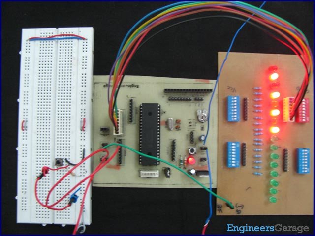
Shoutout to Engineers Garage

In this article you will find:
- Introduction
- What are interruptions?
*External Interruptions | Connections - Setting the code
Shout out to the beautiful Hive community!
In previous editions, we talked about different topics related to:
- Show information on displays.
- Convert analog signals into digital binary code that the microcontroller can understand.
However, now it is time to delve deeper into one of the characteristics of microcontrollers, which we can use for those instances where we want to stop the program and execute an alternative function or simply do two things at the same time.
These are: Interruptions.
So, if you want to know how interruptions work, how they can help you in your projects and how to apply them without problems, you just have to keep reading.
Having said that:
What is an interrupt?
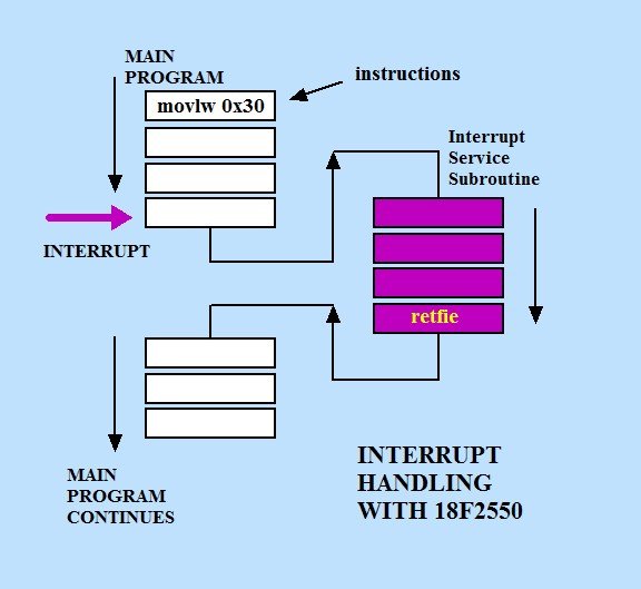
Shoutout to Punto Flotante
The first question you will ask yourself when hearing about interruptis: What is this?
Simply put, interrupts occur when the main program (the one executed in the while loop) stops and skips a few lines until it reaches another function and executes its code.
It is this function that is executed when the interruption of the main program occurs, which is known as the interrupt function or interrupt service routine (ISR), and it will be of great help when we want to execute code outside our program.
But how does our microcontroller do this?
In the first instance, the memory of our microcontroller is made up of two types of memory: Program memory and data memory.
The data memory is that which is equivalent to an SRAM (RAM Memory), which will allow us to store temporary values in the program as long as it is running. Once finished, they are deleted.
This data memory is organized into different memory registers, which we will have to access and change their values if we want to add additional peripherals or configure the program to perform its normal operation.
If we look at the data memory distribution of the PIC16F877A:

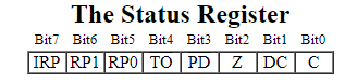
- For example, if in low-level languages like Assembler we want to make all the pins of port B be outputs, we have to access the Status register and set the RP1 bit to 0 and RP0 to 1 (01 is the number 1, which means that we go to memory bank 1).
- Once in memory bank 1, we introduce the value of 00000000 to the TRISB register, indicating that all pins will be output.
Shoutout to PIC16x84 Basics
However, in this case the one that interests us most is the program memory, which contains the program instructions that we write and that we insert into the microcontroller. This is made up of two parts:
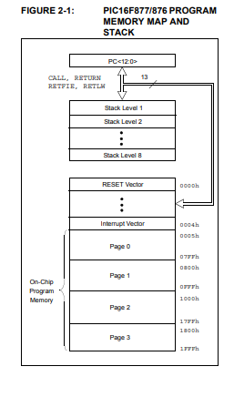
- The program execution vectors, which contain those referring to the pages or lines of the instructions, the Reset vector and the interruption vector, which will stop the execution instructions and take us to the interrupt function.
- The stack, which is the space where the address of the last instruction that was executed before calling the interrupt is stored, so that when the interrupt function ends, we can access the function from which it was called.
As you can see, the stack in the PIC16F877A has 8 levels, so it can store up to 8 addresses. This means that we can execute up to 8 interrupts, each one inside the other.
Now, interruptions in PIC microcontrollers can be separated into two types: External and Internal:
- External interrupts are those interrupts that are produced by an external element, which may be an added peripheral or simply the change of state of one of the pins of the I/O ports configured as inputs.
- The internal ones are the interrupts caused by the change of state of some of the internal peripherals of the PIC, such as the Timers, the CCP module or comparators.
In this case, since we will divide the topic of interrupts with microcontrollers into a few parts, we will start with external interrupts. In this case, we will have the simplest ones, which are the interrupts due to state changes in RB0 and RB4,RB5,RB6,RB7.
External Interrupts | Connections
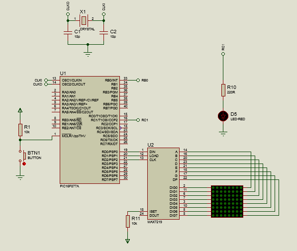
For the first interrupt in which we will make a connection, we will have the interrupt due to a state change in RB0.
In this case, we will create a circuit that will allow us to interrupt the scrolling of a word in an 8x8 LED matrix, during which time we will see a scrolling sequence of 4 LEDs occur.
Once the interrupt finishes executing, the LED matrix word will continue scrolling normally.
The connections will be simple. The DIN, LOAD and CLK pins of the MAX7219 are connected to the RD0, RD1 and RD2 pins, connecting the pins from the segments A to DP to the columns and those from DIG0 to DIG7 to the rows.
As for the connection for the interrupt, we only place a button, connecting it to a pull-down resistor and to the power and finally to pin B0. On Pin C1 the output will be connected to a 220Ω resistor and a Red LED.
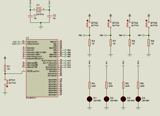
For the second program, where we will use the interrupts with state change in RB4, RB5, RB6 and RB7, we will make pressing a specific button execute a different sequence in 4 LEDs.
For this, buttons connected to the power supply and pull-down resistors are connected to the pins RC0, RC1, RC2 and RC3, while the outputs that will go to the 220Ω resistors with the LEDS.
Thus, we will have the connections to create the two programs. Let's move on to the code.
Setting the code
For the first program where we will interrupt the scrolling in the LED matrix with an LED sequence, we will first look at the configuration:
#include <16f877a.h>
#fuses HS, NOWDT, NOPROTECT, NOPUT, NOLVP, BROWNOUT
#use delay(clock=20M)
#use standard_io(D)
#use fast_io(B)
#use fast_io(C)

#define DATA PIN_D0
#define LOAD PIN_D1
#define CLK PIN_D2
#include <MAX7219.c>

unsigned int8 H[8] = 0, 62, 62, 12, 12, 62, 62, 0;
unsigned int8 HE[8] = 12, 12, 62, 62, 0, 62, 62, 42;
unsigned int8 EL[8] = 0, 62, 62, 42, 0, 62, 62, 48;
unsigned int8 LL[8] = 0, 62, 62, 48, 0, 62, 62, 48;
unsigned int8 LO[8] = 0, 62, 62, 48, 0, 28, 54, 54;
unsigned int8 O[8] = 0, 28, 54, 54, 54, 28, 0, 62;
Here, we can see that we will use a standard configuration, placing the fast_io to B and C to quickly define that B will be dedicated to inputs and C to outputs in the void main.
Next, we define the D port pins dedicated to the DIN, LOAD and CLK pins, finally including the MAX7219 library.
Once this is achieved, we are left to create a series of arrangements that allow us to create the illusion of displacement. If you want to learn how to do this, just see the previous article
Now, before looking at the interrupt function, we must understand how one is created. For this, outside the void main() we add the following tag:
- INT_[Interruption name], which will allow us to determine what type of interrupt to use. This is to avoid confusing the microcontroller if more than one interrupt function is used.
Among some of the interrupt names that we can find:
#define GLOBAL 0xF2C0
#define PERIPH 0xF240
#define INT_RTCC 0x00F220
#define INT_TIMER0 0x00F220
#define INT_TIMER1 0x009D01
#define INT_TIMER2 0x009D02
#define INT_TIMER3 0x00A002
#define INT_EXT_L2H 0x5000F210
#define INT_EXT_H2L 0x6000F210
However, for this one we will use the INT_EXT, since this will be the external interrupt for the state change in B0. Thus, we would have #INT_EXT, which will be followed by a function with any name:
#INT_EXT
void interrupt_function()
{
    // Code Here
}
And it is inside this function that we will place the LED sequence. For this, we enter:
#INT_EXT
void interrupt_function()
{
    for(int i = 0; i < 4; i++)
    {
       output_high(PIN_C1);
       delay_ms(500);
       output_low(PIN_C1);
       delay_ms(500);
    }
}
Which would then take us to the next step: Create the main program:
void main()
{
    set_tris_b(0xFF);
    set_tris_c(0x00);
    display_init(0);
    seg_putc("1");
    enable_interrupts(INT_EXT);
    ext_int_edge(L_TO_H);
    enable_interrupts(GLOBAL);
    output_c(0x00);

    while(TRUE)
    {
       display_digits(H,8);
       delay_ms(400);
       display_digits(HE,8);
       delay_ms(400);
       display_digits(EL,8);
       delay_ms(400);
       display_digits(LL,8);
       delay_ms(400);
       display_digits(LO,8);
       delay_ms(400);
       display_digits(O,8);
       delay_ms(400);
    }
}
Here we can see a series of very important instructions. After determining whether port B and C pins were inputs or outputs and starting the MAX7219 and the matrix, we used:
- enable_interrupts, which allows us to activate the specific type of interrupt we want.
- ext_int_edge, This will be used exclusively when you have the INT_EXT interrupt, which describes that it will be executed by a falling or rising edge on pin B0. Here, if we want it to be rising, we place L_TO_H (Low to High) or H_TO_L (High to Low).
Knowing this, since we will use the external interrupt (Interrupt produced by a change of state in B0), the enable_interrupts(INT_EXT) is placed.
For the edge, we will have a low to high or rising edge, where the interrupt will occur if the state of RB0 changes from low to high.
Finally, we turn on global interrupts, which is essential so that any other interrupts can occur, which is why it is mandatory when using interrupts.
Once we clean port C, we move on to the while loop, where we use the display digits with the different delays to begin showing the different arrangements and therefore, the "movement" of the word in the matrix.
So when looking at the complete program:
#include <16f877a.h>
#fuses HS, NOWDT, NOPROTECT, NOPUT, NOLVP, BROWNOUT
#use delay(clock=20M)
#use standard_io(D)
#use fast_io(B)
#use fast_io(C)

#define DATA PIN_D0
#define LOAD PIN_D1
#define CLK PIN_D2
#include <MAX7219.c>

unsigned int8 H[8] = 0, 62, 62, 12, 12, 62, 62, 0;
unsigned int8 HE[8] = 12, 12, 62, 62, 0, 62, 62, 42;
unsigned int8 EL[8] = 0, 62, 62, 42, 0, 62, 62, 48;
unsigned int8 LL[8] = 0, 62, 62, 48, 0, 62, 62, 48;
unsigned int8 LO[8] = 0, 62, 62, 48, 0, 28, 54, 54;
unsigned int8 O[8] = 0, 28, 54, 54, 54, 28, 0, 62;

#INT_EXT
void interrupt_function()
{
    for(int i = 0; i < 4; i++)
    {
       output_high(PIN_C1);
       delay_ms(500);
       output_low(PIN_C1);
       delay_ms(500);
    }
}

void main()
{
    set_tris_b(0xFF);
    set_tris_c(0x00);
    display_init(0);
    seg_putc("1");
    enable_interrupts(INT_EXT);
    ext_int_edge(L_TO_H);
    enable_interrupts(GLOBAL);
    output_c(0x00);

    while(TRUE)
    {
       display_digits(H,8);
       delay_ms(400);
       display_digits(HE,8);
       delay_ms(400);
       display_digits(EL,8);
       delay_ms(400);
       display_digits(LL,8);
       delay_ms(400);
       display_digits(LO,8);
       delay_ms(400);
       display_digits(O,8);
       delay_ms(400);
    }
}
And when executing:
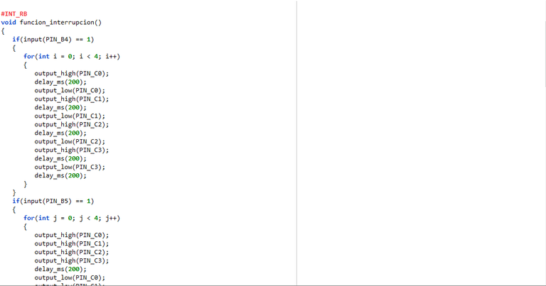
#INT_RB
void interrupt_function()
{
    if(input(PIN_B4) == 1)
    {
       for(int i = 0; i < 4; i++)
       {
          output_high(PIN_C0);
          delay_ms(200);
          output_low(PIN_C0);
          output_high(PIN_C1);
          delay_ms(200);
          output_low(PIN_C1);
          output_high(PIN_C2);
          delay_ms(200);
          output_low(PIN_C2);
          output_high(PIN_C3);
          delay_ms(200);
          output_low(PIN_C3);
          delay_ms(200);
       }
    }
    if(input(PIN_B5) == 1)
    {
       for(int j = 0; j < 4; j++)
       {
          output_high(PIN_C0);
          output_high(PIN_C1);
          output_high(PIN_C2);
          output_high(PIN_C3);
          delay_ms(200);
          output_low(PIN_C0);
          output_low(PIN_C1);
          output_low(PIN_C2);
          output_low(PIN_C3);
          delay_ms(200);
       }
    }
    if(input(PIN_B6) == 1)
    {
       for(int k = 0; k < 4; k++)
       {
          output_high(PIN_C0);
          output_low(PIN_C1);
          output_high(PIN_C2);
          output_low(PIN_C3);
          delay_ms(200);
          output_low(PIN_C0);
          output_high(PIN_C1);
          output_low(PIN_C2);
          output_high(PIN_C3);
          delay_ms(200);
       }
          output_low(PIN_C0);
          output_low(PIN_C1);
          output_low(PIN_C2);
          output_low(PIN_C3);
    }

    if(input(PIN_B7) == 1)
    {
       for(int l = 0; l < 4; l++)
       {
          output_high(PIN_C3);
          delay_ms(200);
          output_low(PIN_C3);
          output_high(PIN_C2);
          delay_ms(200);
          output_low(PIN_C2);
          output_high(PIN_C1);
          delay_ms(200);
          output_low(PIN_C1);
          output_high(PIN_C0);
          delay_ms(200);
          output_low(PIN_C0);
          delay_ms(200);
       }
    }
}
As we can see, in addition to adding the new #INT_RB label, this new function will be made up mainly of conditionals, which will ask us if the state of pins B4, B5, B6 or B7 is high. If one of these is met, one or more LEDs light up, we wait about 200ms and then it alternates.
This will be done for 4 different sequences:
- Once to turn the LEDs on and off from left to right, repeating 4 times.
- One for the 4 LEDs to turn on, wait 200 seconds and then turn off, alternating 4 times.
- The third sequence will turn on LEDs 1 and 3, keeping 2 and 4 off. Wait 200ms and then 2 and 4 turn on, turning off 1 and 3.
- The last one will be the opposite of the first. Here the LEDs will turn on and off from right to left for 4 times.
Once we know this, we just have to look at the void main() and while(True):
void main()
{
    set_tris_b(0xFF);
    set_tris_c(0x00);
    enable_interrupts(INT_RB);
    enable_interrupts(GLOBAL);
    output_low(PIN_C0);
    output_low(PIN_C1);
    output_low(PIN_C2);
    output_low(PIN_C3);

    while(TRUE)
    {
    }
}
We see within the void main() the configurations, placing the pins of port B as inputs and those of port C as outputs. We activate the RB type interrupts (High status of RB4, RB5, RB6 and RB7) and the Global type so that they execute without problems.
Note: We note that ext_int_edge() is not used, since it is not a type of state change interrupt in RB0.
Finally, we guarantee that at the beginning of the program all the LEDs are off with the output_low() instructions.
As for while(TRUE), in this we could write the program we want, since when interrupting the same thing will happen as in the first example. However, here we only verify that the interruption takes place.
So when you have the complete code:
#include <16f877a.h>
#fuses HS, NOWDT, NOPROTECT, NOPUT, NOLVP, BROWNOUT
#use delay(clock=20M)
#use standard_io(D)
#use fast_io(B)
#use fast_io(C)

#INT_RB
void interrupt_function()
{
    if(input(PIN_B4) == 1)
    {
       for(int i = 0; i < 4; i++)
       {
          output_high(PIN_C0);
          delay_ms(200);
          output_low(PIN_C0);
          output_high(PIN_C1);
          delay_ms(200);
          output_low(PIN_C1);
          output_high(PIN_C2);
          delay_ms(200);
          output_low(PIN_C2);
          output_high(PIN_C3);
          delay_ms(200);
          output_low(PIN_C3);
          delay_ms(200);
       }
    }
    if(input(PIN_B5) == 1)
    {
       for(int j = 0; j < 4; j++)
       {
          output_high(PIN_C0);
          output_high(PIN_C1);
          output_high(PIN_C2);
          output_high(PIN_C3);
          delay_ms(200);
          output_low(PIN_C0);
          output_low(PIN_C1);
          output_low(PIN_C2);
          output_low(PIN_C3);
          delay_ms(200);
       }
    }
    if(input(PIN_B6) == 1)
    {
       for(int k = 0; k < 4; k++)
       {
          output_high(PIN_C0);
          output_low(PIN_C1);
          output_high(PIN_C2);
          output_low(PIN_C3);
          delay_ms(200);
          output_low(PIN_C0);
          output_high(PIN_C1);
          output_low(PIN_C2);
          output_high(PIN_C3);
          delay_ms(200);
       }
          output_low(PIN_C0);
          output_low(PIN_C1);
          output_low(PIN_C2);
          output_low(PIN_C3);
    }

    if(input(PIN_B7) == 1)
    {
       for(int l = 0; l < 4; l++)
       {
          output_high(PIN_C3);
          delay_ms(200);
          output_low(PIN_C3);
          output_high(PIN_C2);
          delay_ms(200);
          output_low(PIN_C2);
          output_high(PIN_C1);
          delay_ms(200);
          output_low(PIN_C1);
          output_high(PIN_C0);
          delay_ms(200);
          output_low(PIN_C0);
          delay_ms(200);
       }
    }
}

void main()
{
    set_tris_b(0xFF);
    set_tris_c(0x00);
    enable_interrupts(INT_RB);
    enable_interrupts(GLOBAL);
    output_low(PIN_C0);
    output_low(PIN_C1);
    output_low(PIN_C2);
    output_low(PIN_C3);

    while(TRUE)
    {
    }
}
One of the advantages of using these buttons with interrupts is that we don't have to write debounce code, which if we remember are the lines of code we write to prevent the button from being "pressed" more times than it should and causing errors.
Finally, running the program:
And we can have our interruptions with different sequences.
I hope this article has shown you the world of possibilities that the use of interrupts in our microcontrollers can open up, starting with the simplest: External interrupts.
In the next chapters we will see internal interrupts, which will allow us to create different effects such as generating PWM pulses or using timers, among many others.
In this way, if you want to continue learning and achieve mastery in the management of PICs, we will see you in the next edition of microcontrollers!

Usando Interrupciones
Shoutout to Engineers Garage
En este artículo encontrarás:
- Introducción
- ¿Qué son las interrupciones?
- Interrupciones Externas | Conexiones
- Estableciendo el código
¡Un saludo a la hermosa comunidad de Hive!
En las ediciones previas, hablamos sobre distintos tópicos relacionados a:
- Mostrar información en displays.
- Convertir señales analógicas en código binario digital que el microcontrolador pueda entender.
Sin embargo, ahora es tiempo de adentrarnos más en una de las características propias de los microcontroladores, que podemos usar para aquellas instancias donde queramos detener el programa y ejecutar una función alternativa o simplemente hacer dos cosas al mismo tiempo.
Estas son: Las interrupciones.
Así, si quieres saber como funcionan las interrupciones, como pueden ayudarte en tus proyectos y como aplicarlas sin problemas, solo tienes que seguir leyendo.
Dicho esto:
¿Qué son las interrupciones?
Shoutout to Punto Flotante
La primera pregunta que te harás al escuchar sobre las interrupciones ¿Qué es esto?
Dicho de forma sencilla, las interrupciones ocurren cuando el programa principal (El que se ejecuta en el ciclo while) se detiene y se saltan unas cuantas líneas hasta llegar a otra función y ejecutar su código.
Es a esta función que se ejecuta cuando se produce la interrupción del programa principal a la que se conoce como función de interrupción o rutina de interrupción de servicio (ISR), y nos será de gran ayuda cuando queramos ejecutar código fuera de nuestro programa.
Pero, ¿Cómo lleva a cabo esto nuestro microcontrolador?
En primera instancia, la memoria de nuestro microcontrolador se encuentra formada por dos tipos de memoria: La memoria de programa y la memoria de datos.
La memoria de de datos es aquella que equivale a una SRAM (Memoria RAM), la cual nos permitirá almacenar valores temporales en el programa siempre y cuando se esté ejecutando. Una vez terminado, se borran.
Esta memoria de datos se encuentra organizada en distintos registros de memoria, a los cuales tendremos que acceder y cambiar sus valores si queremos añadir periféricos adicionales o configurar el programa para que realice su operación normal.
Si observamos la distribución de memoria de datos del PIC16F877A:
- Por ejemplo, si en lenguajes de bajo nivel como Assembler queremos hacer que todos los pines del puerto B sean salidas, tenemos que acceder al registro Status y colocar al bit RP1 en 0 y RP0 en 1 (01 es el número 1, lo que significa que nos dirigimos al banco de memoria 1).
- Una vez en el banco de memoria 1, introducimos el valor de 00000000 al registro TRISB, indicando que todos los pines serán de salida.
Shoutout to PIC16x84 Basics
Sin embargo, en este caso la que más nos interesa es la memoria de programa, que contiene las instrucciones del programa que escribimos y que insertamos al microcontrolador. Este está compuesto por dos partes:
- Los vectores de ejecución del programa, que contienen los referentes a las páginas o líneas de las instrucciones, el vector de Reset y el vector de interrupción, el cual detendrá las instrucciones de ejecución y nos llevará a la función de interrupción.
- La pila, que es el espacio donde se guarda la dirección de la última instrucción que se ejecutó antes de llamar a la interrupción, esto para que al terminar la función de interrupción, podramos acceder a la función desde donde se llamó.
Como puedes ver la pila en el PIC16F877A tiene 8 niveles, con lo que puede almacenar hasta 8 direcciones. Esto significa que podemos ejecutar hasta 8 interrupciones, cada una dentro de la otra.
Ahora bien, las interrupciones en microcontroladores PIC pueden separarse en dos tipos: Externas e Internas:
- Las externas son aquellas interrupciones que se producen por un elemento externo, que bien puede ser un periférico añadido o simplemente el cambio de estado de uno de los pines de los puertos de I/O configurados como entradas.
- Las internas son las interrupciones causadas por el cambio de estado de alguno de los periféricos internos del PIC, como pueden ser los Timers, el módulo CCP o comparadores.
En este caso, ya que dividiremos el tema de las interrupciones con microcontroladores en unas cuantas partes, comenzaremos con las interrupciones externas. En este caso, tendremos las más sencillas, que son las interrupciones por cambio de estado en RB0 y en RB4,RB5,RB6,RB7.
Interrupciones Externas | Conexiones
Para la primera interrupción en la que haremos conexión, tendremos la interrupción por cambio de estado en RB0.
En este caso, crearemos un circuito que nos permitirá interrumpir el desplazamiento de una palabra en una matriz LED 8x8, tiempo durante el cual veremos que ocurre una secuencia de desplazamiento de 4 leds.
Una vez termine de ejecutar la interrupción, la palabra de la matriz LED se seguirá desplazando normalmente.
Las conexiones serán algo sencillo. A los pines RD0, RD1 y RD2 se conectan los pines de DIN, LOAD y CLK del MAX7219, conectando los pines los segmentos A hasta DP a las columnas y los de DIG0 hasta DIG7 a las filas.
En cuanto a la conexión para la interrupción, solo colocamos un botón, conectándolo a una resistencia pull-down y a la alimentación y finalmente al pin B0. En el Pin C1 se conectará la salida a una resistencia de 220Ω y un LED Rojo.
Para el segundo programa, donde usaremos las interrupciones con cambio de estado en RB4, RB5, RB6 y RB7, haremos que al presionar un botón específico se ejecute una secuencia distinta en 4 leds.
Para esto, se conectan a los pines RC0,RC1,RC2 y RC3 botones conectados a la alimentación y a resistencias pull-down, mientras que a los pines RB0, RB1, RB2 y RB3 se conectan las salidas que irán hacia las resistencias de 220Ω con los LEDS.
Así, ya tendremos las conexiones para crear los dos programas. Pasemos al código.
Estableciendo el código
Para el primer programa donde interrumpiremos el scroll en la matriz LED con una secuencia del LED, primer observaremos la configuración:
#include <16f877a.h>
#fuses HS, NOWDT, NOPROTECT, NOPUT, NOLVP, BROWNOUT
#use delay(clock=20M)
#use standard_io(D)
#use fast_io(B)
#use fast_io(C)

#define DATA PIN_D0
#define LOAD PIN_D1
#define CLK PIN_D2
#include <MAX7219.c>

unsigned int8 H[8] = 0, 62, 62, 12, 12, 62, 62, 0;
unsigned int8 HE[8] = 12, 12, 62, 62, 0, 62, 62, 42;
unsigned int8 EL[8] = 0, 62, 62, 42, 0, 62, 62, 48;
unsigned int8 LL[8] = 0, 62, 62, 48, 0, 62, 62, 48;
unsigned int8 LO[8] = 0, 62, 62, 48, 0, 28, 54, 54;
unsigned int8 O[8] = 0, 28, 54, 54, 54, 28, 0, 62;
Aquí, podemos ver que usaremos una configuración estándar, colocando el fast_io a B y a C para definir rapidamente que B será dedicado a las entradas y C a las salidas en el void main.
Luego, definimos los pines del puerto D dedicados a los pines de DIN, LOAD y CLK, finalmente incluyendo la librería del MAX7219.
Una vez logrado esto, nos queda crear una serie de arreglos que nos permitan crear la ilusión de desplazamiento. Si quieres aprender como hacer esto, solo tienes que ver el artículo anterior
Ahora, antes de pasar a observar la función de interrupción, debemos de entender como se crea una. Para esto, fuera del void main() añadimos la siguiente etiqueta:
- INT_[Nombre de la interrupción], que nos permitirá determinar que tipo de interrupción se va a usar. Esto para no confundir al microcontrolador en caso de usar más de una función de interrupción.
Entre algunos de los nombres de interrupción que podemos encontrar:
#define GLOBAL                    0xF2C0
#define PERIPH                    0xF240
#define INT_RTCC                  0x00F220
#define INT_TIMER0                0x00F220
#define INT_TIMER1                0x009D01
#define INT_TIMER2                0x009D02
#define INT_TIMER3                0x00A002
#define INT_EXT_L2H               0x5000F210
#define INT_EXT_H2L               0x6000F210
Sin embargo, para esta usaremos el INT_EXT, ya que esta será la interrupción externa para el cambio de estado en B0. Así, tendríamos a #INT_EXT, lo cual vendrá seguida de una función con un nombre cualquiera:
#INT_EXT
void interrupt_function()
{
   // Code Here
}
Y es adentro de esta función que colocaremos la secuencia del LED. Para esto, ingresamos:
#INT_EXT
void interrupt_function()
{
   for(int i = 0; i < 4; i++)
   {
      output_high(PIN_C1);
      delay_ms(500);
      output_low(PIN_C1);
      delay_ms(500);
   }
}
Lo que nos llevaría luego al siguiente paso: Crear el programa principal:
void main()
{
   set_tris_b(0xFF);
   set_tris_c(0x00);
   display_init(0);
   seg_putc("1");
   enable_interrupts(INT_EXT);
   ext_int_edge(L_TO_H);
   enable_interrupts(GLOBAL);
   output_c(0x00);

   while(TRUE)
   {
      display_digits(H,8);
      delay_ms(400);
      display_digits(HE,8);
      delay_ms(400);
      display_digits(EL,8);
      delay_ms(400);
      display_digits(LL,8);
      delay_ms(400);
      display_digits(LO,8);
      delay_ms(400);
      display_digits(O,8);
      delay_ms(400);
   }
}
Aquí podemos ver una serie de instrucciones de suma importancia. Después de determinar si los pines del puerto B y C eran entradas o salidas e iniciar el MAX7219 y la matriz, usamos:
- enable_interrupts, que nos permite activar el tipo de interrupción específica que queramos.
- ext_int_edge, Esta se usará exclusivamente cuando se tenga la interrupción INT_EXT, que describe que esta se ejecutará por un flanco de bajada o subida en el pin B0. Aquí, si queremos que sea de subida, colocamos L_TO_H (De bajo a alto) o H_TO_L (Alto a bajo).
Sabiendo esto, ya que usaremos la interrupción externa (Interrupción producida por un cambio de estado en B0), se coloca el enable_interrupts(INT_EXT).
Para el flanco, tendremos uno de bajo a alto o flanco de subida, donde la interrupción se producirá si el estado de RB0 cambia de bajo a alto.
Finalmente, activamos las interrupciones globales, lo cual es esencial para que cualquier otra interrupción pueda producirse, razón por la que es obligatoria al usar interrupciones.
Una vez limpiamos el puerto C, pasamos al ciclo while, donde usamos el display digits con los distintos delay para comenzar a mostrar los distintos arreglos y por lo tanto, el "movimiento" de la palabra en la matriz.
Con lo que al observar el programa completo:
#include <16f877a.h>
#fuses HS, NOWDT, NOPROTECT, NOPUT, NOLVP, BROWNOUT
#use delay(clock=20M)
#use standard_io(D)
#use fast_io(B)
#use fast_io(C)

#define DATA PIN_D0
#define LOAD PIN_D1
#define CLK PIN_D2
#include <MAX7219.c>

unsigned int8 H[8] = 0, 62, 62, 12, 12, 62, 62, 0;
unsigned int8 HE[8] = 12, 12, 62, 62, 0, 62, 62, 42;
unsigned int8 EL[8] = 0, 62, 62, 42, 0, 62, 62, 48;
unsigned int8 LL[8] = 0, 62, 62, 48, 0, 62, 62, 48;
unsigned int8 LO[8] = 0, 62, 62, 48, 0, 28, 54, 54;
unsigned int8 O[8] = 0, 28, 54, 54, 54, 28, 0, 62;

#INT_EXT
void interrupt_function()
{
   for(int i = 0; i < 4; i++)
   {
      output_high(PIN_C1);
      delay_ms(500);
      output_low(PIN_C1);
      delay_ms(500);
   }
}

void main()
{
   set_tris_b(0xFF);
   set_tris_c(0x00);
   display_init(0);
   seg_putc("1");
   enable_interrupts(INT_EXT);
   ext_int_edge(L_TO_H);
   enable_interrupts(GLOBAL);
   output_c(0x00);

   while(TRUE)
   {
      display_digits(H,8);
      delay_ms(400);
      display_digits(HE,8);
      delay_ms(400);
      display_digits(EL,8);
      delay_ms(400);
      display_digits(LL,8);
      delay_ms(400);
      display_digits(LO,8);
      delay_ms(400);
      display_digits(O,8);
      delay_ms(400);
   }
}
Y al ejecutar:
#INT_RB
void funcion_interrupcion()
{
   if(input(PIN_B4) == 1)
   {
      for(int i = 0; i < 4; i++)
      {
         output_high(PIN_C0);
         delay_ms(200);
         output_low(PIN_C0);
         output_high(PIN_C1);
         delay_ms(200);
         output_low(PIN_C1);
         output_high(PIN_C2);
         delay_ms(200);
         output_low(PIN_C2);
         output_high(PIN_C3);
         delay_ms(200);
         output_low(PIN_C3);
         delay_ms(200);
      }
   }
   if(input(PIN_B5) == 1)
   {
      for(int j = 0; j < 4; j++)
      {
         output_high(PIN_C0);
         output_high(PIN_C1);
         output_high(PIN_C2);
         output_high(PIN_C3);
         delay_ms(200);
         output_low(PIN_C0);
         output_low(PIN_C1);
         output_low(PIN_C2);
         output_low(PIN_C3);
         delay_ms(200);
      }
   }
   if(input(PIN_B6) == 1)
   {
      for(int k = 0; k < 4; k++)
      {
         output_high(PIN_C0);
         output_low(PIN_C1);
         output_high(PIN_C2);
         output_low(PIN_C3);
         delay_ms(200);
         output_low(PIN_C0);
         output_high(PIN_C1);
         output_low(PIN_C2);
         output_high(PIN_C3);
         delay_ms(200);
      }
         output_low(PIN_C0);
         output_low(PIN_C1);
         output_low(PIN_C2);
         output_low(PIN_C3);
   }

   if(input(PIN_B7) == 1)
   {
      for(int l = 0; l < 4; l++)
      {
         output_high(PIN_C3);
         delay_ms(200);
         output_low(PIN_C3);
         output_high(PIN_C2);
         delay_ms(200);
         output_low(PIN_C2);
         output_high(PIN_C1);
         delay_ms(200);
         output_low(PIN_C1);
         output_high(PIN_C0);
         delay_ms(200);
         output_low(PIN_C0);
         delay_ms(200);
      }
   }
}
Como podemos ver, además de agregar el nuevo label de #INT_RB, esta nueva función estará formada principalmente con condicionales, las cuales nos preguntarán si el estado de los pines B4, B5, B6 o B7 está en alto. Si se cumple uno de estos, se encienden uno o varios leds, esperamos unos 200ms y luego se alterna.
Esto se hará para 4 secuencias distintas:
- Una para que se enciendan y apaguen los leds de izquierda a derecha, repitiendo 4 veces.
- Una para que se enciendan los 4 leds, se esperen 200 segundos y luego se apaguen, alternando 4 veces.
- La tercera secuencia hará que se enciendan los LEDS 1 y 3, manteniendo 2 y 4 apagados. Se esperan los 200ms y luego se encienden 2 y 4, apagando 1 y 3.
- La última será el opuesto de la primera. Aquí los leds se encenderán y apagarán de derecha izquierda por 4 veces.
Una vez que sabemos esto, solo tenemos que ver el void main() y el while(True):
void main()
{
   set_tris_b(0xFF);
   set_tris_c(0x00);
   enable_interrupts(INT_RB);
   enable_interrupts(GLOBAL);
   output_low(PIN_C0);
   output_low(PIN_C1);
   output_low(PIN_C2);
   output_low(PIN_C3);

   while(TRUE)
   {
   }
}
Vemos dentro del void main() las configuraciones, colocando los pines del puerto B como entradas y los del puerto C como salidas. Activamos las interrupciones de tipo RB (Estado en alto de RB4, RB5, RB6 y RB7) y las de tipo Global para que se ejecuten sin problemas.
Nota: Notamos que no se usa el ext_int_edge(), ya que no es un tipo de interrupción por cambio de estado en RB0.
Finalmente, garantizamos que al inicio del programa todos los leds están apagados con las instrucciones de output_low().
En cuanto al while(TRUE), en este podríamos escribir el programa que queramos, ya que al interrumpir sucederá lo mismo que en el primer ejemplo. Sin embargo, aquí solo verificamos que la interrupción se lleve a cabo.
Con lo que al tener el código completo:
#include <16f877a.h>
#fuses HS, NOWDT, NOPROTECT, NOPUT, NOLVP, BROWNOUT
#use delay(clock=20M)
#use standard_io(D)
#use fast_io(B)
#use fast_io(C)

#INT_RB
void funcion_interrupcion()
{
   if(input(PIN_B4) == 1)
   {
      for(int i = 0; i < 4; i++)
      {
         output_high(PIN_C0);
         delay_ms(200);
         output_low(PIN_C0);
         output_high(PIN_C1);
         delay_ms(200);
         output_low(PIN_C1);
         output_high(PIN_C2);
         delay_ms(200);
         output_low(PIN_C2);
         output_high(PIN_C3);
         delay_ms(200);
         output_low(PIN_C3);
         delay_ms(200);
      }
   }
   if(input(PIN_B5) == 1)
   {
      for(int j = 0; j < 4; j++)
      {
         output_high(PIN_C0);
         output_high(PIN_C1);
         output_high(PIN_C2);
         output_high(PIN_C3);
         delay_ms(200);
         output_low(PIN_C0);
         output_low(PIN_C1);
         output_low(PIN_C2);
         output_low(PIN_C3);
         delay_ms(200);
      }
   }
   if(input(PIN_B6) == 1)
   {
      for(int k = 0; k < 4; k++)
      {
         output_high(PIN_C0);
         output_low(PIN_C1);
         output_high(PIN_C2);
         output_low(PIN_C3);
         delay_ms(200);
         output_low(PIN_C0);
         output_high(PIN_C1);
         output_low(PIN_C2);
         output_high(PIN_C3);
         delay_ms(200);
      }
         output_low(PIN_C0);
         output_low(PIN_C1);
         output_low(PIN_C2);
         output_low(PIN_C3);
   }

   if(input(PIN_B7) == 1)
   {
      for(int l = 0; l < 4; l++)
      {
         output_high(PIN_C3);
         delay_ms(200);
         output_low(PIN_C3);
         output_high(PIN_C2);
         delay_ms(200);
         output_low(PIN_C2);
         output_high(PIN_C1);
         delay_ms(200);
         output_low(PIN_C1);
         output_high(PIN_C0);
         delay_ms(200);
         output_low(PIN_C0);
         delay_ms(200);
      }
   }
}

void main()
{
   set_tris_b(0xFF);
   set_tris_c(0x00);
   enable_interrupts(INT_RB);
   enable_interrupts(GLOBAL);
   output_low(PIN_C0);
   output_low(PIN_C1);
   output_low(PIN_C2);
   output_low(PIN_C3);

   while(TRUE)
   {
   }
}
Una de las ventajas de usar estos botones con interrupciones es que no tenemos que escribir código para antirrebote, que si recordamos son las líneas de código que escribimos para evitar que el botón se "presione" más veces de las que debería y que cause errores.
Finalmente, ejecutando el programa:
Y podremos tener nuestras interrupciones con distintas secuencias.
Espero que este artículo te haya mostrado el mundo de posibilidades que puede abrir el uso de interrupciones en nuestros microcontroladores, comenzando con las más sencillas: Las interrupciones externas.
En los próximos capítulos veremos las interrupciones internas, las cuales nos permitirán crear distintos efectos como la generación de pulsos PWM o usar temporizadores, entre muchas otras.
De esta forma, si quieres seguir aprendiendo y alcanza la maestría en el manejo de PICs, ¡Nos veremos en la siguiente edición de microcontroladores!
Thanks for your contribution to the STEMsocial community. Feel free to join us on discord to get to know the rest of us!
Please consider delegating to the @stemsocial account (85% of the curation rewards are returned).
You may also include @stemsocial as a beneficiary of the rewards of this post to get a stronger support.
Congratulations @jesalmofficial! You have completed the following achievement on the Hive blockchain And have been rewarded with New badge(s)
Your next target is to reach 30000 upvotes.
You can view your badges on your board and compare yourself to others in the Ranking
If you no longer want to receive notifications, reply to this comment with the word
STOPCheck out our last posts:
a la pucha se ve complicado de hacer :D yo que antes pensaba que era facil
Feliz año nuevo amigo dobro. Haré todo lo posible para que el próximo artículo sea más fácil de entender. Sigue con el excelente trabajo.
¡Saludos!