Creating scrolling text with an LED Matrix - Creando Texto desplazante con una matriz LED - Microcontroladores #9 [EN/ES]
Creating airport signs
Shoutout to PIC Microcontroller

In this article you'll find:
- Introduction
- What is the MAX7219?
- Connections
- Setting the code
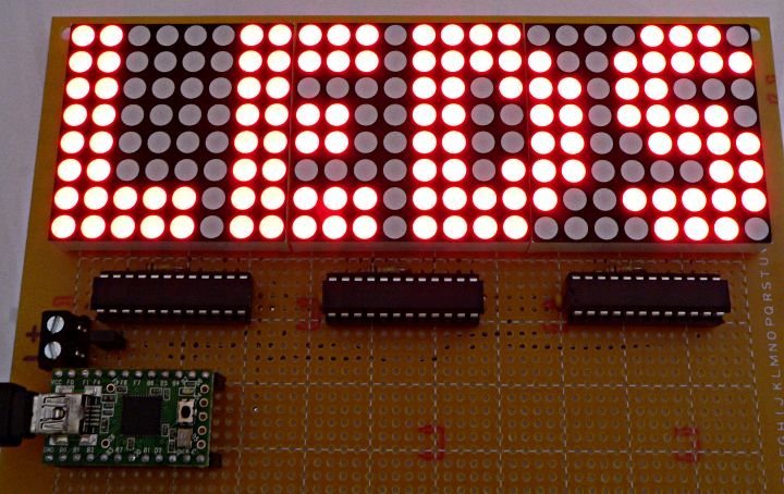
Greetings to all!
In the previous edition we talked about LED matrices, groupings of a large number of LEDs, arranged in the form of columns and rows to display symbols, numbers, letters, etc...
It is here that we learned how we could create, both directly and through an integrated device called MAX7219, the characters that we wanted to display.
However, so far we have only shown how to generate one character at a time, immediately changing to the other, which is still far from the words that move from left to right in airports.
This is why in this article, using a MAX7219, we will learn how to create a scroll effect in a word, so that in this way, we can place any message we want on our LED matrices.
Thus,
What is the MAX7219?
Shoutout to LarryD in the Arduino Forum
Although we already described what the MAX7219 is briefly in the previous article, knowing how it works is valuable information.
The Max7219 is an 8-bit driver, used to serve as an interface between microcontrollers and common cathode displays that can be 7-segment displays, bar displays, or 64 individual LEDs, such as those found in 8x8 LED matrices.
This integrated device is made up of a series of components, such as a B-code BCD decoder (from 0 to 9), multiplexers, different registers for the Decoder address and, vitally, an internal SRAM memory that allows storing the characters that will be sent to the display.
As we already know, what makes the MAX7219 so valuable is the fact that it drastically reduces the number of pins that we must use in our microcontroller, requiring only 3, which will be connected to the Data inputs (DIN), LOAD and Clock (CLK).
If we look at the functional diagram:
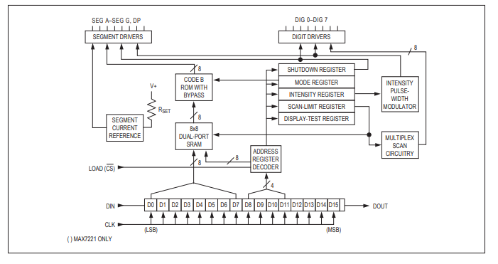
Shoutout to Analog Devices
In our case, once connected to a display and guided by a microcontroller, the bits from DIG0 to DIG7 will execute the multiplexing or scanning, while those from A to G will send the character information in the device's RAM.
Now that we know a little more about the composition of the MAX7219 without going into many technical details, we can move on to observe what the connections of our program would be like.
Connections
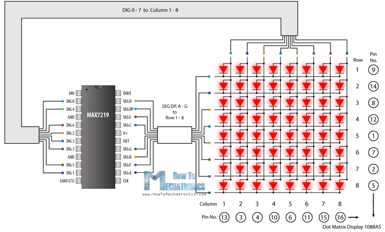
In the previous article, we looked at the connection of the PIC16f877A microcontroller with the MAX7219 and then the display. In this case, the connections will be really similar, with one small difference:
Where we can notice that the only difference is the connections of segments A to DP, dedicated to the columns, where previously A was connected to DIG7, B to DIG6 and so on in reverse. In this case, the connections will be A with DIG0, B with DIG1, continuing until reaching the last connection. This is done so that the sequence that we will show in the matrix is not seen inverted. If placed in the first way, it would look like this:
Where we see that the message is completely reversed, which is why we use the new connection.
In this way, we can move on to what is most important for this scroll effect: The program.
Setting the code
Remembering the previous article, the library that we included in our IDE for the MAX7219, MAX7219.c, includes the following instructions:
- display_init() ; To indicate that the display/matrix is started, placing a 0 or 1 as a parameter depending on whether it is a common cathode or common anode.
- seg_putc() ; With this we select the display or matrix that we select, in case of multiplexing more than one. (Place numbers in string form. Ex: "1")
- display_char(); It allows us to display a letter or character in a simple way in the matrix, as long as it is entered as a string.
In addition to these, we have another instruction which can help us display decimal values without having to convert them to the DataType "char". This instruction is:
- display_digits() ; With this we can show any decimal value that we insert. In case of using arrays, we can insert as parameters the array value and the number of elements we want to display.
If we view the display_digits in a similar way to the arrays we created for characters in direct connections, then this is basically the same thing. In our case, we will take different arrangements and show them at different times to create the illusion of scrolling.
For our program, we intend to create a scroll effect displaying the "Hello" message, so in addition to using our program to create arrays and create an array for each letter, we will have to create more arrays for the letter combinations to as they move.
Thus, if we observe the resulting arrangements, we can notice:
unsigned int8 H[8] = 0, 62, 62, 12, 12, 62, 62, 0;
unsigned int8 HE[8] = 12, 12, 62, 62, 0, 62, 62, 42;
unsigned int8 EL[8] = 0, 62, 62, 42, 0, 62, 62, 48;
unsigned int8 LL[8] = 0, 62, 62, 48, 0, 62, 62, 48;
unsigned int8 LO[8] = 0, 62, 62, 48, 0, 28, 54, 54;
unsigned int8 O[8] = 0, 28, 54, 54, 54, 28, 0, 62;
Which, as we can notice, are of type int8 (Integer formed by 8 bits), and when transforming these to binary, we can notice:
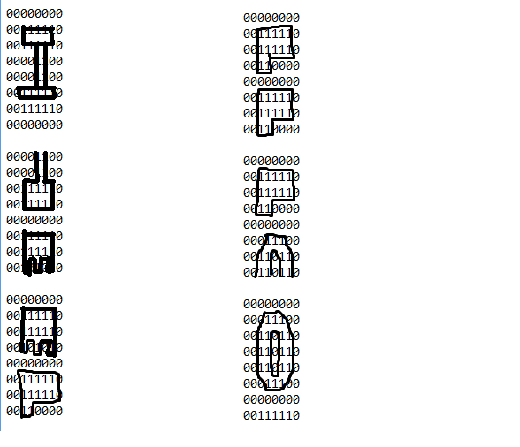
That we will have the sequence at different points with these arrangements. Once created, we just have to go to void main and start the display and select the segment. Then, within the while, we start using display_digits, to display the 8 elements of the arrays we created at each point, giving them a small delay of 400ms between them so that we can observe the sequence in motion:
void main()
{
    display_init(0);
    seg_putc("1");

    while(TRUE)
    {
       display_digits(H,8);
       delay_ms(400);
       display_digits(HE,8);
       delay_ms(400);
       display_digits(EL,8);
       delay_ms(400);
       display_digits(LL,8);
       delay_ms(400);
       display_digits(LO,8);
       delay_ms(400);
       display_digits(O,8);
       delay_ms(400);
    }
}
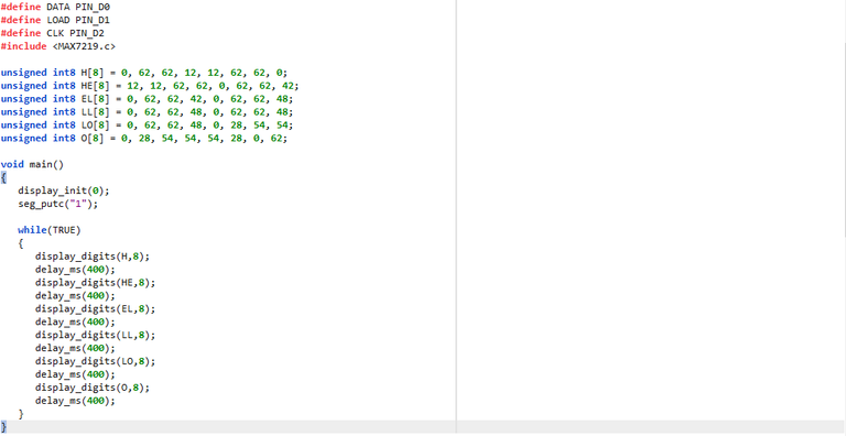
So the complete program would look like this:
#include <16f877a.h>
#fuses HS, NOWDT, NOPROTECT, NOPUT, NOLVP, BROWNOUT
#use delay(clock=20M)
#use standard_io(D)

#define DATA PIN_D0
#define LOAD PIN_D1
#define CLK PIN_D2
#include <MAX7219.c>

unsigned int8 H[8] = 0, 62, 62, 12, 12, 62, 62, 0;
unsigned int8 HE[8] = 12, 12, 62, 62, 0, 62, 62, 42;
unsigned int8 EL[8] = 0, 62, 62, 42, 0, 62, 62, 48;
unsigned int8 LL[8] = 0, 62, 62, 48, 0, 62, 62, 48;
unsigned int8 LO[8] = 0, 62, 62, 48, 0, 28, 54, 54;
unsigned int8 O[8] = 0, 28, 54, 54, 54, 28, 0, 62;

void main()
{
    display_init(0);
    seg_putc("1");

    while(TRUE)
    {
       display_digits(H,8);
       delay_ms(400);
       display_digits(HE,8);
       delay_ms(400);
       display_digits(EL,8);
       delay_ms(400);
       display_digits(LL,8);
       delay_ms(400);
       display_digits(LO,8);
       delay_ms(400);
       display_digits(O,8);
       delay_ms(400);
    }
}
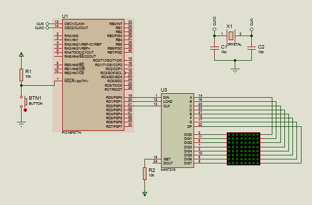
Remembering that we must define the CLK, DATA and LOAD pins for the library to work. Thus, when we run our simulation, we will have:
And we can see our text in movement or "scroll"
As you can see, once we use the MAX7219 in our matrix, everything becomes easier, just having to create the different points where the displacement occurs. Now, you can create scroll effects without problems.
I couldn't have created this article without the help of @electronico, who gave me useful advice on how to display information in my posts and his articles were a great inspiration for the creation of this one.
If you want to see his article on how to create character strings and the scroll effect with the PIC16F877A, you just have to click here
I hope this post has been helpful to you and that we can now manage different types of displays effectively. That said, see you in the next edition of microcontrollers and:

Creando letreros de aeropuerto
Shoutout to PIC Microcontroller
Introducción:
- Introducción
- ¿Qué es el MAX7219?
- Conexiones
- Estableciendo el código
¡Un saludo a todos!
En la edición previa hablamos sobre las matrices LED, agrupaciones de un gran número de LEDs, ordenados en forma de columnas y filas para mostrar símbolos, números, letras, etc...
Es aquí, que conocimos como podíamos crear, tanto de manera directa como por medio de un integrado llamado MAX7219, los caracteres que quisieramos mostrar.
Sin embargo, hasta ahora solo hemos mostrado como generar un caracter a la vez, cambiando inmediatamente al otro, cosa que aún dista de las palabras que se mueven de izquierda a derecha en los aeropuertos.
Es por esto, que en este artículo, por medio de un MAX7219, aprenderemos a crear un efecto de scroll en una palabra, para que de esta forma, podamos colocar cualquier mensaje que deseemos en nuestras matrices LED.
De esta forma,
¿Qué es el MAX7219?
Shoutout to LarryD in the Arduino Forum
A pesar de que ya describimos que es el MAX7219 de manera breve en el artículo previo, el conocer como funciona es de valiosa información.
El Max7219 es un driver de 8 bits, usado para servir de interfaz entre microcontroladores y displays de cátodo común que bien pueden ser displays de 7 segmentos, de barras o 64 leds individuales, como son los que se encuentran en las matrices LED 8x8.
Este integrado está formado por una serie de componentes, como lo son un decodificador BCD de código B (De 0 a 9), multiplexores, distintos registros para dirección de Decoder y, de forma vital, una memoria SRAM interna que permite almacenar los caracteres que se enviarán al display.
Como ya sabemos, lo que hace tan valioso al MAX7219 es el hecho de que reduce de forma drástica la cantidad de pines que debemos de usar en nuestro microcontrolador, requiriendo de tan solo 3, que irán conectados a las entradas de Data (DIN), LOAD y la de Reloj (CLK).
Si observamos el diagrama funcional:
Shoutout to Analog Devices
En nuestro caso, una vez conectado a un display y guiado por un microcontrolador, los bits de DIG0 a DIG7 ejecutarán el multiplexado o barrido, mientras que los de A a la G enviarán la información de los caracteres en la RAM del dispositivo.
Ahora que sabemos un poco más sobre la composición del MAX7219 sin entrar en muchos detalles técnicos, podemos pasar a observar como serían las conexiones de nuestro programa.
Conexiones
En el artículo previo, observamos la conexión del microcontrolador PIC16f877A con el MAX7219 y luego el display. En este caso, las conexiones serán realmente similares, con una pequeña diferencia:
Donde podemos notar que la única diferencia son las conexiones de los segmentos A hasta DP, dedicados a las columnas, donde antes se conectaba A con DIG7, B con DIG6 y así de manera inversa. En este caso, las conexiones serán A con DIG0, B con DIG1, siguiendo hasta llegar a la última conexión. Esto se realiza para que no se observe invertida la secuencia que mostraremos en la matriz. De colocarse de la primera forma, se vería de la siguiente manera:
Donde vemos que el mensaje se invierte totalmente, razón por la que usamos la nueva conexión.
De esta forma, podemos pasar a lo más importante para este efecto de scroll: El programa.
Estableciendo el código
Recordando el artículo previo, la librería que incluíamos a nuestro IDE para el MAX7219, la MAX7219.c, trae las siguientes instrucciones:
- display_init() ; Para indicar que se inicia el display/matriz, colocando un 0 o un 1 como parámetro dependiendo de si es de cátodo común o ánodo común.
- seg_putc() ; Con este seleccionamos el display o matriz que seleccionemos, en caso de multiplexar más de uno. (Colocar números en forma de string. Ej: "1")
- display_char(); Nos permite mostrar una letra o caracter de forma sencilla en la matriz, siempre y cuando se introduzca como una string.
Además de estas, tenemos otra instrucción la cual nos puede ayudar a mostrar valores decimales sin tener que convertirlos al DataType "char". Esta instrucción es:
- display_digits() ; Con esta podemos mostrar cualquier valor decimal que insertemos. En caso de usar arreglos, podemos insertar como parámetros el valor de arreglo y el número de elementos que queremos mostrar.
Si vemos el display_digits de forma similar a la que veíamos los arreglos que creabamos para los caracteres en las conexiones directas, entonces este es básicamente lo mismo. En nuestro caso, tomaremos distintos arreglos y los mostraremos en distintos tiempos para crear la ilusión de scroll.
Para nuestro programa, pretendemos crear un efecto de scroll mostrando el mensaje de "Hello", por lo que, además de recurrir a nuestro programa para crear matrices y crear un arreglo para cada letra, tendremos que crear más arreglos para las combinaciones de letras a medida que se desplazan.
Así, si observamos los arreglos resultantes, podremos notar:
unsigned int8 H[8] = 0, 62, 62, 12, 12, 62, 62, 0;
unsigned int8 HE[8] = 12, 12, 62, 62, 0, 62, 62, 42;
unsigned int8 EL[8] = 0, 62, 62, 42, 0, 62, 62, 48;
unsigned int8 LL[8] = 0, 62, 62, 48, 0, 62, 62, 48;
unsigned int8 LO[8] = 0, 62, 62, 48, 0, 28, 54, 54;
unsigned int8 O[8] = 0, 28, 54, 54, 54, 28, 0, 62;
Los cuales, como podemos notar, son de tipo int8 (Entero formado por 8 bits), y que al transformar estos a binario, podremos notar:
Que tendremos la secuencia en distintos puntos con estos arrreglos. Una vez creados, solo tenemos que ir al void main e iniciar el display y seleccionar el segmento. Luego, dentro del while, comenzamos usando a display_digits, para mostrar los 8 elementos de los arreglos que creamos en cada punto, dándoles un pequeño retardo de 400ms entre ellos para que podamos observar la secuencia en movimiento:
void main()
{
   display_init(0);
   seg_putc("1");

   while(TRUE)
   {
      display_digits(H,8);
      delay_ms(400);
      display_digits(HE,8);
      delay_ms(400);
      display_digits(EL,8);
      delay_ms(400);
      display_digits(LL,8);
      delay_ms(400);
      display_digits(LO,8);
      delay_ms(400);
      display_digits(O,8);
      delay_ms(400);
   }
}
Con lo que tendríamos que el programa completo se vería de la siguiente manera:
#include <16f877a.h>
#fuses HS, NOWDT, NOPROTECT, NOPUT, NOLVP, BROWNOUT
#use delay(clock=20M)
#use standard_io(D)

#define DATA PIN_D0
#define LOAD PIN_D1
#define CLK PIN_D2
#include <MAX7219.c>

unsigned int8 H[8] = 0, 62, 62, 12, 12, 62, 62, 0;
unsigned int8 HE[8] = 12, 12, 62, 62, 0, 62, 62, 42;
unsigned int8 EL[8] = 0, 62, 62, 42, 0, 62, 62, 48;
unsigned int8 LL[8] = 0, 62, 62, 48, 0, 62, 62, 48;
unsigned int8 LO[8] = 0, 62, 62, 48, 0, 28, 54, 54;
unsigned int8 O[8] = 0, 28, 54, 54, 54, 28, 0, 62;

void main()
{
   display_init(0);
   seg_putc("1");

   while(TRUE)
   {
      display_digits(H,8);
      delay_ms(400);
      display_digits(HE,8);
      delay_ms(400);
      display_digits(EL,8);
      delay_ms(400);
      display_digits(LL,8);
      delay_ms(400);
      display_digits(LO,8);
      delay_ms(400);
      display_digits(O,8);
      delay_ms(400);
   }
}
Recordando que debemos de definir los pines CLK, DATA y LOAD para que la librería funcione. Así, al ejecutar nuestra simulación, tendremos:
Y podremos ver nuestro texto en desplazamiento o "scroll"
Como puedes ver, una vez que usamos el MAX7219 en nuestra matriz, todo se facilita, solo teniendo que crear los distintos puntos en que se produce el desplazamiento. Ahora, podrás crear efectos de scroll sin problemas.
No podría haber creado este artículo sin la ayuda @electronico, quien me dió utiles consejos sobre como mostrar la información en mis posts y sus artículos fueron de gran inspiración para la creación de este.
Si quieres ver su artículo sobre como crear cadenas de caracteres y el efecto de scroll con el PIC16F877A, solo tienes que clickear aquí
Espero que este post les haya servido de ayuda y que ahora podamos manejar distintos tipos de display efectivamente. Dicho esto, nos vemos en la siguiente edición de microntroladores y:
Amazing how to code the lights to get light! Thanks for showing us that
`
Want to Know more about Hivepakistan?
Ping Us On Hive Pakistan Discord server
To support HivePakistan, delegate Hive Power to hivepakistan and earn 90% curation reward :)
Here are some handy links for delegation
A delegation of 500 or more HP makes you earn Hivepakistan supporter badge.
`
No problem. Thank you for reading.
Have a very blessed Christmas.
Thanks for your contribution to the STEMsocial community. Feel free to join us on discord to get to know the rest of us!
Please consider delegating to the @stemsocial account (85% of the curation rewards are returned).
You may also include @stemsocial as a beneficiary of the rewards of this post to get a stronger support.
Hola amigo, un post interesante. La verdad es que el driver MAX7219 es muy versátil, solo con tres pines se conecta al microcontrolador, que bien, eso es increíble.Saludos
Mucha razón amigo, con el MAX7219 podemos conectar incluso varios displays al microcontrolador con los mismos 3 pines.
Eso es muy bueno, lástima que aquí en Cuba es difícil conseguir eso tipos de componentes electrónicos, aquí hay que reciclar jj. Saludos
Comprendo tu situación. Aquí en Venezuela también es muy difícil conseguirlos, sobre todo los microcontroladores PIC y ni se digan matrices LED.
Recuerdo que para un proyecto tuve que recurrir a hacer la matriz con 64 Leds Individuales.
Excelentes artículos sobre reparación, me inspiran a hacer artículos sobre circuitos físicos en físico en un futuro. Saludos.
Congratulations @jesalmofficial! You have completed the following achievement on the Hive blockchain And have been rewarded with New badge(s)
Your next target is to reach 100 upvotes.
You can view your badges on your board and compare yourself to others in the Ranking
If you no longer want to receive notifications, reply to this comment with the word
STOPCheck out our last posts: