Creating Figures and Symbols in an LCD Screen | Creando figuras y símbolos en una pantalla LCD - Microcontrollers #2 [EN/ES]
Using Special Characters
Shoutout to Programming Digest

In this article you will find:
- Introduction
- CGRAM memory
- How are characters recorded in CGRAM?
- Creating a custom character in code
Shout out to the beautiful Hive community!
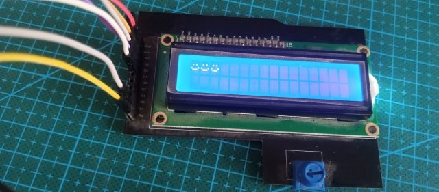
On this occasion, we will continue with the management of LCD Displays, which allow us to display information on their screens with low voltage consumption.
In this small article, we will see another of the functionalities of these peripherals, which is:
- Creating custom characters.
This means that if we want to create a symbol that is not in the Display's memory, we can do so if we take into account some instructions and memory addresses.
This way, if you want to create figures, symbols or some object to display on the LCD screen, you just have to continue reading. Having said that:
CGRAM memory
Shoutout to Controllerstech
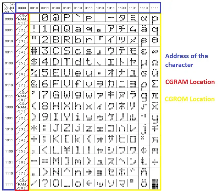
The first thing we must understand in order to create a special character on our LCD display is how its memory is distributed, which is distributed in different addresses, among which we can mostly find the conventional signs of the ASCII code stored.
However, to create characters that are not registered here, we will have to access other memory addresses, which are known as CGRAM.
CGRAM stands for Character Generator RAM, since it allows us to store custom characters in temporary memory. If we look at the following image:
Shoutout to hoopstar on Arduino Forum
Here we can see that if the memory addresses are identified by 8-bit binary numbers (For example: 01011010), then those corresponding to the CGRAM will be those whose 4 most significant bits (That is, the first 4 bits reading from left to right ) have the sequence 0000.
These memory addresses will be 8 for each segment or row, which will be selected according to the last 4 bits (Least Significant Bits).
Now that we know what the CGRAM addresses are, we have to see how the characters are recorded within them.
How are characters recorded in CGRAM?
Shoutout to Embedded Engineering
Once we send the CGRAM address where we want to save the character to the LCD, it will take information that we provide and based on this, it will begin to "draw" or record the character.
For example, if we wanted to type the custom character "b":
Shoutout to electronicsforu.com
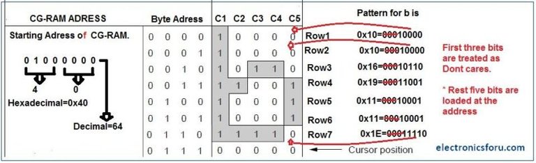
Here, if we interpret each box or character as a matrix of 5 columns and 8 rows, we will only have to fill each row with the correct values to obtain the character we are looking for.
- The 4 bits on the left, known as Byte Address, identify the row of the matrix where the characters to be recorded are located.
- The other 5 bits (Which will be introduced as an 8-bit string where the value of the first 3 will not matter) are those that will have the values that we will assign to each row of the matrix.
Thus, we note that for Byte Address 0000 (First row), the binary 00010000 will be recorded, as in address 1000 (Second row), this sequence will continue until the entire character is filled, changing the content of the rows according to be required to create the figure in b.
Now, recapitulating:
- First, the addresses of the CGRAM where the character is intended to be stored will be sent to the LCD.
- An array is introduced with 5-bit values for the 8 rows of the matrix.
- The LCD in write mode will use 4 bits as a pointer to scroll through the 8 rows of the character, writing the values of the array in each one.
- This will be saved in the indicated CGRAM address and we will have our new character.
We identify how everything works at a more detailed level. However, if we wanted to apply it in high-level code, this would be much simpler. Let's observe:
Creating a custom character in code
If we remember the previous article, we know that we will have a series of instructions in the LCD16x2.c library, which allows us to control the LCD. These are:
- lcd_init(), which starts the display.
- lcd_gotoxy(), with which we can choose the row and column of the display screen where we are going to write the data.
- lcd_putc(), Which allows us to write the character that we indicate to the display.
- lcd_clear(), to clear the display.
However, to use CGRAM and create custom characters, 3 other instructions are used, among which we have:
- CGRAM_position(), where we select precisely the position of the CGRAM memory where we want to record the character.
- CGRAM_create_char(), this is where we will create the character, introducing as a parameter the array where we will have the values for the character matrix.
- CGRAM_putc(), with which we introduce the character from the CGRAM to the display.
Thus, if we saw this in practice with a program to count the value of a bird's wing beats, we would have:
#include <16f877a.h>
#fuses HS, NOWDT, NOPROTECT, NOPUT, NOLVP, BROWNOUT
#use delay(clock=20M)
#use standard_io(D)

#define LCD_DB4 PIN_D4
#define LCD_DB5 PIN_D5
#define LCD_DB6 PIN_D6
#define LCD_DB7 PIN_D7
#define LCD_RS PIN_D2
#define LCD_E PIN_D3
#include <LCD_16X2.c>

char array1[8] = {0x00,0x00,0x00,0x0A,0x15,0x04,0x00,0x00};
char array2[8] = {0x00,0x00,0x11,0x0A,0x04,0x04,0x00,0x00};
int value = 0;
Where if we observe, we continue to largely use the code from the previous article. With the first 4 lines we include the 16f877a library, configure the header pins, assign the oscillator frequency and configure port D and its pins for later use.
Then, with the defines we remember to give a new name to the pins of port D, which coincide with those we placed in the library and then, with the #include <LCD_16X2.c> we introduce the LCD library in the program to be able to use the commands.
The variables created will be of great importance, since with these we will assign values to the CGRAM memory to create the characters and make a counter.
- The first array [array1], represents the first frame of an animation that we will create for the flutter. Here, we will have the values for each row, which we will write with the CGRAM_create_char.
- The second arrangement [arrangement2], will be the next frame, where the bird will flap down.
- The value variable will be the counter, which we will increase each time the animation repeats.
For example, if we took the first array into account and assigned it to an array, we would see the following:
00000
00000
00000
01010
10101
00100
00000
00000
Which is interpreted as the bird lowering its wings. However, if we want to create the matrix without having to carry out a tedious bit counting process, we only have to use the LCD Character Creator program, with which we can paint our figure and obtain the resulting arrangement below.
For example, repeating this in LCD Character Creator, we would see:
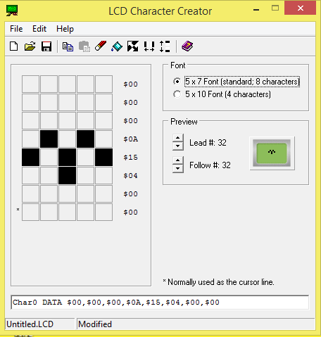
Where if we take the values of Char0 from Data, we will have the basic characters. In order to convert them to a hexadecimal value that our PIC understands, we just have to change the $ symbol to a 0x. So, this results in:
char array1[8] = {0x00,0x00,0x00,0x0A,0x15,0x04,0x00,0x00};
And if we do the same for the bird with its wings up:
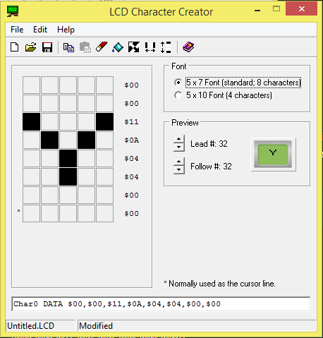
Resulting in:
char array2[8] = {0x00,0x00,0x11,0x0A,0x04,0x04,0x00,0x00};
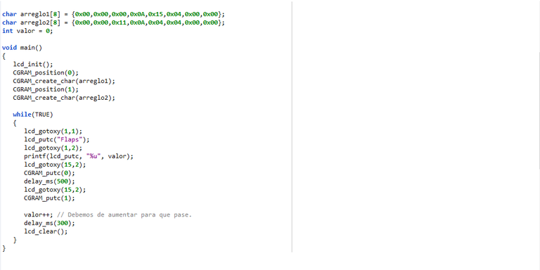
Now, if we look at the body of the program:
void main()
{
    lcd_init();
    CGRAM_position(0);
    CGRAM_create_char(array1);
    CGRAM_position(1);
    CGRAM_create_char(array2);

    while(TRUE)
    {
       lcd_gotoxy(1,1);
       lcd_putc("Flaps");
       lcd_gotoxy(1,2);
       printf(lcd_putc, "%u", value);
       lcd_gotoxy(15,2);
       CGRAM_putc(0);
       delay_ms(500);
       lcd_gotoxy(15,2);
       CGRAM_putc(1);

       value++; // We must increase it for it to happen.
       delay_ms(300);
       lcd_clear();
    }

}
The first thing we will do is start the lcd with lcd_init(). Then, with CGRAM_Position, we select the CGRAM address we want to access, which in this case will be 0 (00000000).
Then, with CGRAM_create_char(), we take the value of the array we created for the bird and save it in the CGRAM position we indicated.
We repeat this process for the second position of the CGRAM, where we will now save the second arrangement.
Once inside the while loop, we go to the first row and first column with lcd_gotoxy and with lcd_putc we place the "Flaps" message, to indicate the wings of the bird.
Subsequently, we go to the second row in the first column and with printf we use a format string for the lcd_putc command with %u, which will act as a container for an unsigned integer, which is precisely the integer we created for the counter.
Note: If you want to know what the Data types will be like for the format strings, you just have to see the following image:
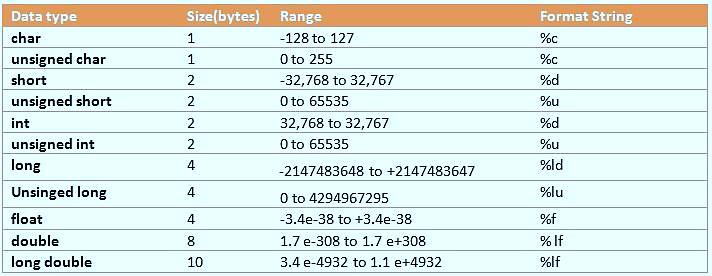
Shoutout to Eitworld from Medium
Then, we will go to column 15 in row 2 and with CGRAM_putc(0), we will place the first animation for the bird's flap, which was saved in position 0 of the CGRAM.
With a delay of 500ms, we wait half a second before moving to the next animation and accessing exactly the same position (15.2) and refreshing the character with the second animation.
After doing this we use value++ to increase the value variable by 1, which will be reflected once the screen is refreshed, for which we will wait about 300ms and then we will execute a lcd_clear to clear the entire screen.
In this way, the complete program would look like this:
#include <16f877a.h>
#fuses HS, NOWDT, NOPROTECT, NOPUT, NOLVP, BROWNOUT
#use delay(clock=20M)
#use standard_io(D)

#define LCD_DB4 PIN_D4
#define LCD_DB5 PIN_D5
#define LCD_DB6 PIN_D6
#define LCD_DB7 PIN_D7
#define LCD_RS PIN_D2
#define LCD_E PIN_D3
#include <LCD_16X2.c>

char array1[8] = {0x00,0x00,0x00,0x0A,0x15,0x04,0x00,0x00};
char array2[8] = {0x00,0x00,0x11,0x0A,0x04,0x04,0x00,0x00};
int value = 0;

void main()
{
    lcd_init();
    CGRAM_position(0);
    CGRAM_create_char(array1);
    CGRAM_position(1);
    CGRAM_create_char(array2);

    while(TRUE)
    {
       lcd_gotoxy(1,1);
       lcd_putc("Flaps");
       lcd_gotoxy(1,2);
       printf(lcd_putc, "%u", value);
       lcd_gotoxy(15,2);
       CGRAM_putc(0);
       delay_ms(500);
       lcd_gotoxy(15,2);
       CGRAM_putc(1);

       value++; // We must increase it for it to happen.
       delay_ms(300);
       lcd_clear();
    }
}
And, when executing:
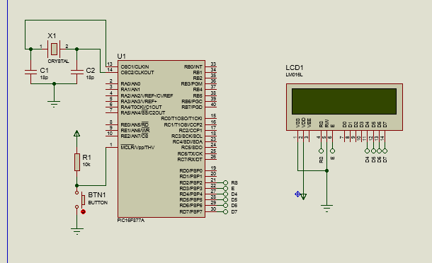
Program connection
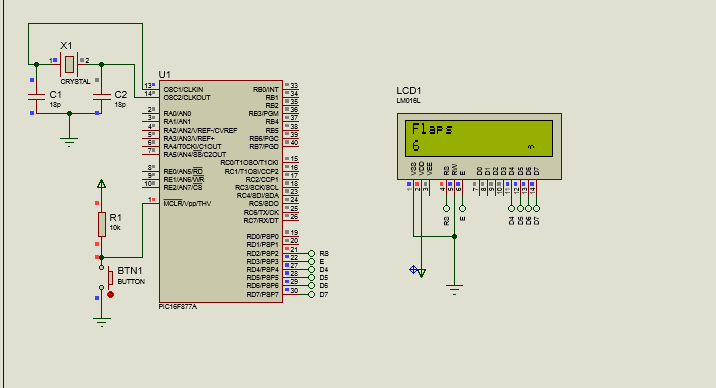
Simulation: Bird with wings down
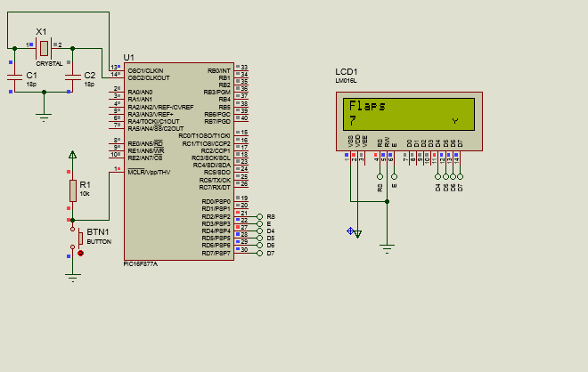
Simulation: Bird with wings up
As you can see, managing LCD screens with PICs does not have to be complicated, relegating the most tedious tasks to the configuration and equipment required to introduce the program.
However, the program itself is not at all complicated and allows us to see quite efficiently how new characters can be created on the LCD.
In this way, we can make animations, place characters that would not otherwise be recognized and many other things on the LCD. However, so far we have only seen the 2x16 LCDs, so we are left to look at the 4x20 LCDs.
Thus, we will see each other in the next Microcontrollers article and:
Used Programs:
- CCS C Compiler (PIC C Compiler)
- Proteus 8 Professional
- LCD Character Creator (Download here)

Usando Caracteres Especiales
Shoutout to Programming Digest
En este artículo encontrarás:
- Introducción
- La memoria CGRAM
- ¿Cómo se graban los caracteres en la CGRAM?
- Creando un caracter personalizado en código
¡Un saludo a la hermosa comunidad de Hive!
En esta ocasión, continuaremos con el manejo de los Displays LCD, los cuales nos permiten mostrar información en sus pantallas con un bajo consumo de voltaje.
En este pequeño artículo, veremos otra de las funcionalidades de estos periféricos, la cual es:
- La creación de caracteres personalizados.
Esto significa que si queremos crear algún símbolo que no se encuentre en la memoria del Display, podremos hacerlo si tomamos en cuenta algunas instrucciones y direcciones de memoria.
De esta forma, si quieres crear figuras, símbolos o algún objeto que mostrar en la pantalla LCD, solo tienes que seguir leyendo. Dicho esto:
La memoria CGRAM
Shoutout to Controllerstech
Lo primero que debemos de entender para poder crear un caracter especial en nuestro display LCD es como se distribuye su memoria, la cual está repartida en distintas direcciones, entre las cuales podemos encontrar en su mayoría los signos convencionales del código ASCII guardados.
Sin embargo, para crear caracteres que no se encuentren registrados aquí, tendremos que acceder a otras direcciones de memoria, las cuales se conocen como CGRAM.
CGRAM significa Character Generator RAM, ya que esta nos permite almacenar caracteres personalizados en la memoria temporal. Si observamos la siguiente imagen:
Shoutout to hoopstar on Arduino Forum
Aquí podemos ver que si las direcciones de memoria se identifican por números binarios de 8 bits (Por ejemplo: 01011010), entonces las correspondientes a la CGRAM serán aquellos cuyos 4 bits más significativos (Es decir, los 4 primeros bits leyendo de izquierda a derecha) tengan la secuencia 0000.
Estas direcciones de memoria serán 8 para cada segmento o fila, las cuales se seleccionarán de acuerdo a los 4 últimos bits (Bits menos significativos).
Ahora que sabemos cuales son las direcciones CGRAM, tenemos que ver como se graban los caracteres dentro de estas.
¿Cómo se graban los caracteres en la CGRAM?
Shoutout to Embedded Engineering
Una vez que enviamos la dirección CGRAM donde queremos guardar el caracter al LCD, este tomará información que le proporcionemos y en base a esto, comenzará a "dibujar" o grabar el caracter.
Por ejemplo, si quisieramos escribir el caracter personalizado "b":
Shoutout to electronicsforu.com
Aquí, si interpretamos cada cuadro o caracter como una matriz de 5 columnas y 8 filas, solo tendremos que rellenar cada fila con los valores correctos para obtener el caracter que buscamos.
- Los 4 bits de la izquierda, conocidos como Byte Address, identifican la fila de la matriz donde se encuentran los caracteres a grabar.
- Los otros 5 bits (Que serán introducidos como una cadena de 8 bits donde el valor de los 3 primeros no importará) son aquellos que tendrán los valores que asignaremos a cada fila de la matriz.
Así, notamos que para el Byte Address 0000 (Primera fila), se grabará el binario 00010000, al igual que en la dirección 1000 (Segunda fila), esta secuencia seguirá hasta que se llene todo el caracter, cambiando el contenido de las filas según sea requerido para crear la figura de la b.
Ahora bien, recapitulando:
- Primero, se enviarán al LCD las direcciones de la CGRAM donde se pretende guardar el caracter.
- Se introduce un arreglo con los valores de 5 bits para las 8 filas de la matriz.
- El LCD en modo escritura usará 4 bits como puntero para desplazarse por las 8 filas del caracter, escribiendo los valores del arreglo en cada una.
- Esto se guardará en la direccion CGRAM indicada y tendremos nuestro nuevo caracter.
Identificamos como funciona todo a un nivel más detallado. Sin embargo, si quisieramos aplicarlo en código de alto nivel, esto sería mucho más sencillo. Observemos:
Creando un caracter personalizado en código
Si recordamos el artículo anterior, sabemos que tendremos una serie de instrucciones en la librería LCD16x2.c, que nos permite manejar al LCD. Estas son:
- lcd_init(), que inicia el display.
- lcd_gotoxy(), con el que podemos escoger la fila y la columna de la pantalla del display donde vamos a escribir los datos.
- lcd_putc(), Que nos permite escribir el caracter que le indiquemos al display.
- lcd_clear(), para limpiar el display.
Sin embargo, para el uso de la CGRAM y la creación de caracteres personalizados, se usan otras 3 instrucciones, entre las que tenemos:
- CGRAM_position(), donde seleccionamos justamente la posición de la memoria CGRAM donde queremos grabar el caracter.
- CGRAM_create_char(), aquí es donde crearemos el caracter, introduciendo como parámetro el arreglo donde tendremos los valores para la matriz del caracter.
- CGRAM_putc(), con el cual introducimos en el display el caracter desde la CGRAM.
Así, si vieramos esto en práctica con un programa para contar el valor de los aleteos de un ave, tendremos:
#include <16f877a.h>
#fuses HS, NOWDT, NOPROTECT, NOPUT, NOLVP, BROWNOUT
#use delay(clock=20M)
#use standard_io(D)

#define LCD_DB4 PIN_D4
#define LCD_DB5 PIN_D5
#define LCD_DB6 PIN_D6
#define LCD_DB7 PIN_D7
#define LCD_RS PIN_D2
#define LCD_E PIN_D3
#include <LCD_16X2.c>

char arreglo1[8] = {0x00,0x00,0x00,0x0A,0x15,0x04,0x00,0x00};
char arreglo2[8] = {0x00,0x00,0x11,0x0A,0x04,0x04,0x00,0x00};
int valor = 0;
Donde si observamos, seguimos utilizando en gran manera el código del artículo anterior. Con las primeras 4 líneas incluimos la librería del 16f877a, configuramos los pines de cabecera, asignamos la frecuencia del oscilador y configuramos el puerto D y sus pines para su uso posterior.
Luego, con los defines recordamos colocarle un nuevo nombre a los pines del puerto D, que coinciden con los que le colocamos en la librería y luego, con el #include <LCD_16X2.c> introducimos la librería del LCD en el programa para poder usar los comandos.
Las variables creadas serán de gran importancia, ya que con estas será que asignaremos valores a la memoria CGRAM para crear los caracteres y hacer un contador.
- El primer arreglo [arreglo1], representa el primer frame de una animación que crearemos para el aleteo. Aquí, tendremos los valores para cada fila, que escribiremos con el CGRAM_create_char.
- El segundo arreglo [arreglo2], será el siguiente frame, donde el ave aleteará hacia abajo.
- La variable valor será el contador, el cual aumentaremos cada vez que se repita la animación.
Por ejemplo, si tomamos en cuenta el primer arreglo y lo asignaramos a una matriz, veríamos lo siguiente:
00000
00000
00000
01010
10101
00100
00000
00000
Lo cual se interpreta como el ave bajando las alas. Sin embargo, si queremos crear la matriz sin tener que realizar un proceso tedioso de conteo de bits, solo tenemos que usar el programa LCD Character Creator, con el que podemos pintar nuestra figura y obtener debajo el arreglo resultante.
Por ejemplo, repitiendo esto en el LCD Character Creator, veríamos:
Donde si tomamos los valores de Char0 de Data, tendremos los caracteres basic. En orden de pasarlos a un valor hexadecimal que entienda nuestro PIC, solo tenemos que cambiar el símbolo de $ por un 0x. Así, esto resulta en:
char arreglo1[8] = {0x00,0x00,0x00,0x0A,0x15,0x04,0x00,0x00};
Y si hacemos lo mismo para el ave con las alas arriba:
Que resulta en:
char arreglo2[8] = {0x00,0x00,0x11,0x0A,0x04,0x04,0x00,0x00};
Ahora bien, si observamos el cuerpo del programa:
void main()
{
   lcd_init();
   CGRAM_position(0);
   CGRAM_create_char(arreglo1);
   CGRAM_position(1);
   CGRAM_create_char(arreglo2);

   while(TRUE)
   {
      lcd_gotoxy(1,1);
      lcd_putc("Flaps");
      lcd_gotoxy(1,2);
      printf(lcd_putc, "%u", valor);
      lcd_gotoxy(15,2);
      CGRAM_putc(0);
      delay_ms(500);
      lcd_gotoxy(15,2);
      CGRAM_putc(1);

      valor++; // Debemos de aumentar para que pase.
      delay_ms(300);
      lcd_clear();
   }

}
Lo primero que haremos será iniciar el lcd con lcd_init(). Luego, con CGRAM_Position, seleccionamos la dirección de CGRAM a la que queremos acceder, que en este caso será la 0 (00000000).
Luego, con CGRAM_create_char(), tomamos el valor del arreglo que creamos para el ave y lo guardamos en la posición de la CGRAM que indicamos.
Repetimos este proceso para la segunda posición de la CGRAM, donde ahora guardaremos al segundo arreglo.
Una vez dentro del ciclo while, nos dirigimos a la primera fila y primera columna con lcd_gotoxy y con lcd_putc colocamos el mensaje de "Flaps", para indicar los aleteos del ave.
Posteriormente, nos dirigimos a la segunda fila en la primera columna y con printf usamos una format string para el comando lcd_putc con %u, que actuará como un contenedor para un unsigned integer, que justamente es el entero que creamos para el contador.
Nota: Si quieres saber como serán los Data types para los format strings, solo tienes que ver la siguiente imagen:
Shoutout to Eitworld from Medium
Luego, iremos a la columna 15 en la fila 2 y con CGRAM_putc(0), colocaremos la primera animación para el aleteo del ave, que fue guardada en la posicion 0 de la CGRAM.
Con un delay de 500ms, esperamos medio segundo antes de pasar a la siguiente animación y acceder justo a la misma posición (15,2) y refrescar el caracter con la segunda animación.
Después de realizar esto usamos valor++ para aumentar justamente la variable valor en 1, lo cual será reflejado una vez que se refresque la pantalla, para lo cual esperaremos unos 300ms y luego ejecutaremos un lcd_clear para limpiar toda la pantalla.
De esta forma, el programa completo se vería de la siguiente manera:
#include <16f877a.h>
#fuses HS, NOWDT, NOPROTECT, NOPUT, NOLVP, BROWNOUT
#use delay(clock=20M)
#use standard_io(D)

#define LCD_DB4 PIN_D4
#define LCD_DB5 PIN_D5
#define LCD_DB6 PIN_D6
#define LCD_DB7 PIN_D7
#define LCD_RS PIN_D2
#define LCD_E PIN_D3
#include <LCD_16X2.c>

char arreglo1[8] = {0x00,0x00,0x00,0x0A,0x15,0x04,0x00,0x00};
char arreglo2[8] = {0x00,0x00,0x11,0x0A,0x04,0x04,0x00,0x00};
int valor = 0;

void main()
{
   lcd_init();
   CGRAM_position(0);
   CGRAM_create_char(arreglo1);
   CGRAM_position(1);
   CGRAM_create_char(arreglo2);

   while(TRUE)
   {
      lcd_gotoxy(1,1);
      lcd_putc("Flaps");
      lcd_gotoxy(1,2);
      printf(lcd_putc, "%u", valor);
      lcd_gotoxy(15,2);
      CGRAM_putc(0);
      delay_ms(500);
      lcd_gotoxy(15,2);
      CGRAM_putc(1);

      valor++; // Debemos de aumentar para que pase.
      delay_ms(300);
      lcd_clear();
   }
}
Y, al ejecutar:
Conexión del programa
Simulación: Ave con alas abajo
Simulación: Ave con alas arriba
Como puedes ver, el manejo de pantallas LCD con PICs no tiene por qué ser algo complicado, relegando las tareas más tediosas a la configuración y equipos requeridos para introducir el programa.
Sin embargo, el programa en si es para nada complicado y nos permite ver de manera bastante eficiente como se pueden crear nuevos caracteres en la LCD.
De esta forma, podremos realizar animaciones, colocar caracteres que de otra forma no serían reconocidos y muchas otras cosas en la LCD. Sin embargo, hasta ahora solo hemos visto los LCD de 2x16, por lo que nos queda ver los LCD 4x20.
Así, nos veremos en el siguiente artículo de Microcontroladores y:
Programas Usados:
- CCS C Compiler (PIC C Compiler)
- Proteus 8 Professional
- LCD Character Creator (Descargar aquí)
Congratulations @jesalmofficial! You have completed the following achievement on the Hive blockchain And have been rewarded with New badge(s)
Your next target is to reach 250 posts.
You can view your badges on your board and compare yourself to others in the Ranking
If you no longer want to receive notifications, reply to this comment with the word
STOPTo support your work, I also upvoted your post!
Check out our last posts:
Thanks for your contribution to the STEMsocial community. Feel free to join us on discord to get to know the rest of us!
Please consider delegating to the @stemsocial account (85% of the curation rewards are returned).
You may also include @stemsocial as a beneficiary of the rewards of this post to get a stronger support.