ADC Conversion | Conversión ADC - Microcontrollers #3 [EN/ES]
What does my computer do with what goes into my microphone?
Shoutout to Seeed Studio

In this article you'll find:
- Introduction
- What is ADC?
- Sampling
- Quantification
- Encoding
Greetings to all!
Until now, when working with microcontrollers we have only seen how to work with LCD Screens. However, now we will take a step forward and take a look at a very important internal component for the PIC.
This component is the ADC, which is of utmost importance when connecting to sensors and transducers, where the aim is to convert the electrical signals provided into digital information with which the microcontroller can work.
Even if this edition will be totally theoretical, it will be very useful for subsequent articles, where we will talk about how to use this type of conversion in our microcontrollers.
In this way, if you want to know how the conversion of analog signals to digital signals is carried out in a simple way, you just have to continue reading. Having said that:
What is ADC?
Shoutout to PCB Design & Analysis - Cadence
Before answering this question, we have to know why an ADC should be used.
When we work with any digital equipment, such as our cell phones, computers or tablets, they must constantly interact with the external world. For this communication to be carried out, the signals that come from the outside world must be taken (such as the sound of our voice towards a speaker or the touch of our finger on a screen) through a sensor, which It will send an electrical signal that will be translated into a language that the processor can understand, this being the binary language, or language of 1s and 0s.
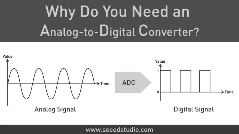
Now, in order to carry out this conversion, what is known as an Analog Digital converter is used, which is responsible for taking an analog signal, which is simply a voltage signal, with a continuous amplitude (that is, , which has voltage values that change constantly over time) and converts it into a discrete digital signal, which is a signal where the information is represented with two values (1 and 0), which, according to the value it has , can be easily interpreted by the microcontroller.
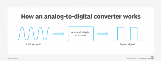
Looking at this graphically:
Shoutout to TechTarget
As we can see, the analog signal on the left, which varies with time (Do not confuse with an AC signal, since ADCs and microcontrollers only work with DC voltage), passes through the ADC and is transformed into the signal with two states: High and Low, which we see on the right, this being the digital signal, which in itself is a train of pulses that represents a binary sequence.
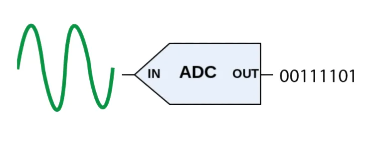
Example:
A 5V signal passes through a 10-bit ADC and is converted to the value of 1023 (1111111111), which the microcontroller can work with.
ADC conversion has a very important parameter, known as resolution, which is simply the smallest increment required to go from one level to another. A level is simply the value in bits that represents a specific quantity in the ADC. For example, the value 512 (1000000000) in a 10-bit ADC is one level.
Now, the number of resolution bits of an adc (Levels) can be calculated simply by using the following formula:
resolution_bits = 2^n
Where n refers to the number of bits of the ADC. If we have a 10-bit ADC, we would have 1024 possible levels, ranging from 0 to 1023.
And to calculate the resolution, the following formula is used:
Resolution = Vref/resolution_bits
Vref refers to full scale, which is the maximum voltage value that will represent the highest level of the ADC. For example, if Vref is 5V, that means that for the 10-bit ADC, the value of 1023 will equal 5V.
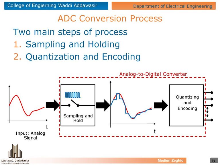
Now, this entire conversion process, which in our view is instantaneous (Conversion times are usually 40 microseconds), is based on a series of stages, which allow us to take the analog signal and convert it to digital.
These are:
- Sampling
- Retention
- Quantification
- Encoding
Now, we will look at each of these:
Sampling
Shoutout to AlazarTech
The sampling stage is based on a simple precept: Taking samples of the analog signal at different moments in time.
If we had a signal like the one we see in the following figure:
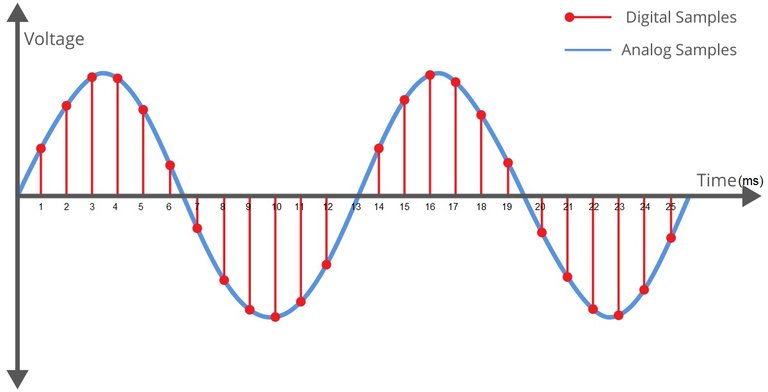
Shoutout to AlazarTech
We can see that it is a sinusoidal signal where the independent variable will be time and the dependent variable will be voltage. Here, each of the separators will represent 1ms, a value that we can take to determine a very important variable during the sampling process: The sampling frequency.
If we want to calculate the sampling frequency of our ADC in this case, we only need to take into account the equation for the frequency, which will be 1/T (That is, one over the period) and we use the time between each period as the period. one of the moments where a sample is taken. So, for our 1ms, we would have a sampling rate of 1kHz.
    1
_______ = 1000
1x10^-3
Thus, we can say that if we insert a sinusoidal signal, which varies between 0 and 5V towards the ADC, the first thing we will do is take, according to the sampling frequency, different sample values following a certain time.
Note: If we want a reliable reproduction of the signal, the Nyquist criterion (Which I will explain in a later article) tells us that we must make the sampling frequency at least double the maximum frequency of the signal.
After this, what happens?
The retention process begins, which is not complex enough to require a mathematical explanation. In this, the samples that we capture during the sampling process are taken and a retention circuit is used to prevent the information from being lost while waiting for the quantification stage.
Quantification
Shoutout to All About Circuits
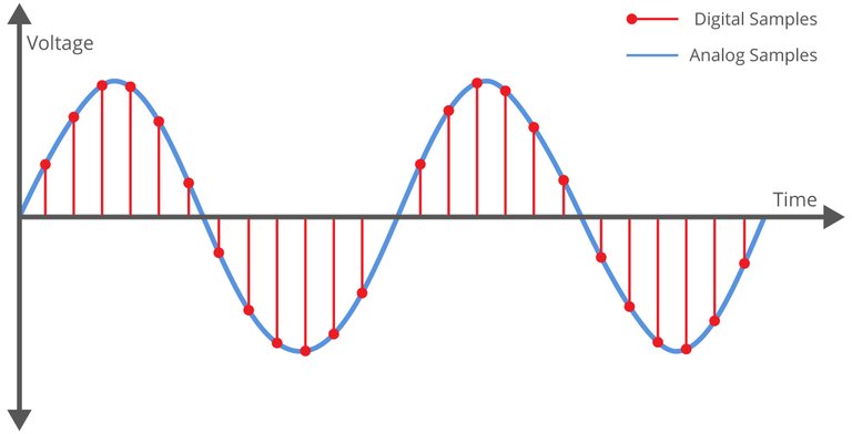
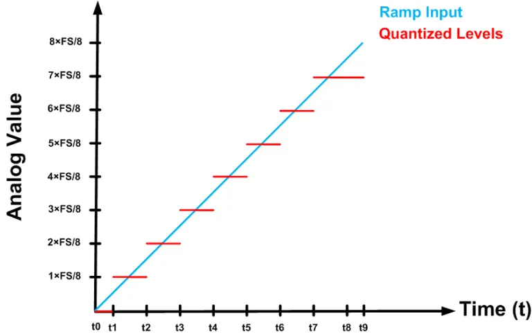
During the quantification stage, we take the samples we acquired during the sampling process and assign them a finite value.
For this, we take the following image and observe that on the vertical axis we will have the values in volts, which in this case are represented as decimals. Knowing that if we transformed the highest number of these levels (As we call each of these separations) to binary, we would have 111, so we confirm that the hypothetical ADC has 3 bits.
Shoutout to Electrical Technology
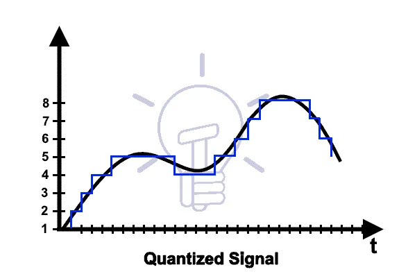
So, we know that according to the time spaces in t, we will take a sample every millisecond, which in this case was approximately 28 samples. Then, we proceed to add the sampling connection lines.
As we can see, the red lines that reach the certain points of the signal do not coincide with the blue steps. This is because the levels on the vertical axis, whose separation is determined by the resolution (The voltage between each bit) does not coincide with the samples taken with respect to the signal.
To reach an easy solution to this, we simply assign the value of the closest level to the sample. For example, for the first one, where the sample point is between 0 and 1, we assign it the value of 1, since the closest value to the point is that of level 1.
Now, this difference that exists between the sample point and the level to be assigned is what is known as quantization error, which largely depends on the number of bits and therefore, levels.
The more levels we have, the greater the resolution and therefore the precision of the measurements, reducing the quantification error. If, for example, we had 4 bits (Which means that the highest value will be 16), this means that we would have 16 levels and therefore a much smaller quantization error.
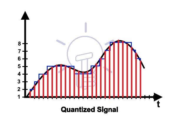
We repeat this approximation process in each sample and end with the following sequence:
1, 2, 3, 3, 4, 4, 4, 4, 4, 4, 4, 3, 3, 3, 3, 4, 4, 5, 6, 7, 7, 7, 7, 7, 6, 5, 4
What represents the quantification of all the samples taken.
Coding
Shoutout to Delphia Evans in SlidePlayer
The coding process is somewhat simple. It simply consists of taking the quantized analog values from the quantization process, translating them into binary code, and passing it into a sequence of bits that comprises the microcontroller or device being used.
For this, we take a look again at our quantified values:
1, 2, 3, 3, 4, 4, 4, 4, 4, 4, 4, 3, 3, 3, 3, 4, 4, 5, 6, 7, 7, 7, 7, 7, 6, 5, 4
And we begin the translation into binary code. We know that 1 = 01, 2 = 10 and so we follow the sequence until 7 = 111. In this way, we have:
001,010,011,011,100,100,100,100,100,100,100,011,011,011,011,100,100,101,110,111,111,111,111,111,1 10, 101, 100
What will become a sequence of ones and zeros (Known as a pulse train), which will represent our final data.
Thus, when the microcontroller receives the signal, it will come in the form of a sequence represented by binary code:
001
010
011
011
100
100
100
100
100
100
100
011
011
011
011
100
100
101
110
111
111
111
111
111
110
101
100
Depending on how you plan to use it, you can use a DAC (Digital to Analog Converter) to obtain a reconstructed signal with a certain margin of error, or simply act on the information.
In this way, we would have our digital signal converted.
I hope this small article has been useful in understanding the ADC process, which will be vitally important to understand subsequent articles.
Even if I could go into much more detail regarding ADC conversion and use examples such as Audio conversion, with sample rates of 44100Hz and 65535 levels (16 bits are used), this will be enough to understand how it can be applied in a PIC, which has internal ADC converters, this type of operation.
In this way, we will see you in the next edition of Microcontrollers, where we will see how to apply this ADC conversion in code. Having said that:

¿Qué hace mi computadora con lo que entra en mi micrófono?
Shoutout to Seeed Studio
In this article you'll find:
- Introducción
- ¿Qué es ADC?
- Muestreo
- Cuantificación
- Codificación
¡Un saludo a todos!
Hasta ahora, al trabajar con microcontroladores solo hemos visto como trabajar con Pantallas LCD. Sin embargo, ahora daremos un paso adelante y daremos un vistazo a un componente interno muy importante para el PIC.
Este componente es el ADC, el cual es de suma importancia al conectarnos a sensores y transductores, donde se busca convertir las señales eléctricas proporcionadas en información digital con la que el microcontrolador pueda trabajar.
Aún si esta edición será totalmente teórica, será de gran utilidad para los artículos posteriores, donde hablaremos sobre como usar este tipo de conversión en nuestros microcontroladores
De esta forma, si quieres saber como se lleva a cabo la conversión de señales analógicas a digitales de manera sencilla, solo tienes que seguir leyendo. Dicho esto:
¿Qué es ADC?
Shoutout to PCB Design & Analysis - Cadence
Antes de responder esta pregunta, tenemos que saber por qué se debe de usar un ADC.
Cuando trabajamos con cualquier equipo digital, como nuestros celulares, computadores o tablet, estos deben de interactuar constantemente con el mundo externo. Para que esta comunicación pueda llevarse a cabo, se deben de tomar las señales que provienen del mundo exterior (Cómo lo son el sonido de nuestra voz hacia una bocina o el toque de nuestro dedo en una pantalla) por medio de un sensor, el cual enviará una señal eléctrica que se traducirá a un lenguaje que pueda entender el procesador, este siendo el lenguaje binario, o lenguaje de los 1 y 0.
Ahora bien, en orden de llevar esta conversión a cabo, se usa lo que se conoce como un conversor Analógico Digital, el cual se encarga de tomar una señal analógica, la cual es simplemente una señal de voltaje, con una amplitud continua (Es decir, que tiene un valores de voltaje que cambian constantemente con el tiempo) y la convierte en una señal digital discreta, que es una señal donde la información se representa con dos valores (1 y 0), la cual, de acuerdo al valor que tenga, puede ser interpretada por el microcontrolador facilmente.
Observando esto de manera gráfica:
Shoutout to TechTarget
Como podemos observar, la señal análoga de la izquierda, que varía con el tiempo (No confundir con una señal en AC, ya que ya los ADC y microcontroladores solo trabajan con voltaje DC), pasa por el ADC y se transforma en la señal con dos estados: Alto y Bajo, que vemos a la derecha, siendo esta la señal digital, que en si es un tren de pulsos que representa una secuencia binaria.
Ejemplo:
Una señal de 5V pasa por un ADC de 10 bits y se convierte en el valor de 1023 (1111111111), con el que puede trabajar el microcontrolador.
La conversión ADC posee un parámetro muy importante, que se conoce como resolución, que es simplemente el incremento más pequeño requerido para pasar de un nivel a otro. Un nivel es simplemente el valor en bits que represente una cantidad específica en el ADC. Por ejemplo, el valor 512 (1000000000) en un ADC de 10 bits, es un nivel.
Ahora bien, el número de bits de resolución de un adc (Niveles) pueden calcularse con tan solo usar la siguiente fórmula:
bits_resolución = 2^n
Donde n se refiere a la cantidad de bits del ADC. Si tenemos un ADC de 10 bits, tendríamos 1024 niveles posibles, que van del 0 al 1023.
Y para calcular la resolución, se usa la siguiente fórmula:
Resolution = Vref/bits_resolución
Vref se refiere al fondo de escala, que es el valor máximo de voltaje que representará el nivel más alto del ADC. Por ejemplo, si Vref vale 5V, eso significa que para el ADC de 10 bits, el valor de 1023 equivaldrá a 5V.
Ahora bien, todo este proceso de conversión, que a nuestra vista es instantáneo (Los tiempos de conversión suelen ser de 40 microsegundos), se basa en una serie de etapas, que nos permiten tomar la señal análoga y pasarla a digital.
Estas son:
- Muestreo
- Retención
- Cuantificación
- Codificación
Ahora, veremos cada una de estas:
Muestreo
Shoutout to AlazarTech
La etapa de muestreo se basa en un simple precepto: El tomar muestras de la señal analógica en distintos instantes de tiempo.
Si tuvieramos una señal como la que vemos en la siguiente figura:
Shoutout to AlazarTech
Podemos ver que es una señal sinusoidal donde la variable independiente será el tiempo y la variable dependiente será el voltaje. Aquí, cada uno de los separadores representará 1ms, valor que podemos tomar para determinar una variable muy importante durante el proceso de muestreo: La frecuencia de muestreo.
Si queremos calcular cual es la frecuencia de muestreo de nuestro ADC en este caso, solo hace falta tomar en cuenta la ecuación para la frecuencia, que será 1/T (Es decir, uno sobre el período) y usamos como período el tiempo entre cada uno de los instantes donde se toma una muestra. Así, para nuestros 1ms, tendríamos una frecuencia de muestreo de 1kHz.
   1
_______  =  1000
1x10^-3
Así, podemos decir que si insertamos una señal sinusoidal, que varía entre 0 y 5V hacia el ADC, lo primero que haremos será tomar, de acuerdo a la frecuencia de muestreo, distintos valores de muestra siguiendo un tiempo determinado.
Nota: Si queremos una reprodución fidedigna de la señal, el criterio de Nyquist (Que explicaré en un articulo posterior) nos dice que debemos hacer la frecuencia de muestreo al menos el doble de la frecuencia máxima de la señal.
Luego de esto, ¿Qué sucede?
Comienza el proceso de retención, el cual no es lo suficientemente complejo como para requerir una explicación matemática. En este, se toman las muestras que capturamos durante el proceso de muestreo y se usa un circuito de retención para evitar que la información se pierda mientras se espera a la etapa de cuantificación.
Cuantificación
Shoutout to All About Circuits
Durante la etapa de cuantificación, tomamos las muestras que adquirimos durante el proceso de muestreo y les asignamos un valor finito.
Para esto, tomamos la siguiente imagen y observamos que en el eje vertical tendremos los valores en voltios, que en este caso están representados como decimales. Sabiendo que si transformaramos el número más alto de estos niveles (Como llamamos a cada una de estas separaciones) a binario, tendríamos 111, por lo que confirmamos que el ADC hipotético tiene 3 bits.
Shoutout to Electrical Technology
Entonces, sabemos que de acuerdo a los espacios de tiempo en t, tomaremos una muestra cada milisegundo, que en este caso fueron un aproximado de 28 muestras. Luego, procedemos a agregar las líneas de la conexión del muestreo.
Como podemos ver, las líneas rojas que llegan hasta los determinados puntos de la señal no coinciden con los escalones azules. Esto se debe, a que los niveles en el eje vertical, cuya separación esta determinada por la resolución (El voltaje que hay entre cada bit) no coincide con las muestras tomadas respecto a la señal.
Para llegar a una solución facil a esto, simplemente, asignamos como valor a la muestra el del nivel más cercano. Por ejemplo, para la primera, donde el punto de la muestra se encuentra entre 0 y 1, le asignamos el valor de 1, puesto que el valor más cercano al punto es el del nivel 1.
Ahora bien, esta diferencia que existe entre el punto de la muestra y el nivel que se va a asignar es lo que se conoce como error de cuantificación, el cual depende en gran manera de la cantidad de bits y por lo tanto, de niveles.
Mientras más niveles tengamos, mayor será la resolución y por lo tanto la precisión de las medidas, reduciendo el error de cuantificación. Si por ejemplo, tuvieramos 4 bits (Lo que significa que el valor más alto será de 16), esto significa que tendríamos 16 niveles y por lo tanto un error de cuantificación mucho más reducido.
Repetimos este proceso de aproximación en cada muestra y terminamos con la siguiente secuencia:
1, 2, 3, 3, 4, 4, 4, 4, 4, 4, 4, 3, 3, 3, 3, 4, 4, 5, 6, 7, 7, 7, 7, 7, 6, 5, 4
Lo que nos representa la cuantificación de todas las muestras tomadas.
Codificación
Shoutout to Delphia Evans in SlidePlayer
El proceso de codificación es algo sencillo. Simplemente consiste en tomar los valores analógicos cuantificados del proceso de cuantificación, traducirlos a código binario y pasarlo a una secuencia de bits que comprenda el microcontrolador o dispositivo que se esté usando.
Para esto, echamos un vistazo de nuevo a nuestros valores cuantificados:
1, 2, 3, 3, 4, 4, 4, 4, 4, 4, 4, 3, 3, 3, 3, 4, 4, 5, 6, 7, 7, 7, 7, 7, 6, 5, 4
Y comenzamos la traducción a código binario. Sabemos que 1 = 01, 2 = 10 y así seguimos la secuencia hasta 7 = 111. De esta forma, tenemos:
001, 010, 011, 011, 100, 100, 100, 100, 100, 100, 100, 011, 011, 011, 011, 100, 100, 101, 110, 111, 111, 111, 111, 111, 110, 101, 100
Lo que se convertirá en una secuencia de unos y ceros (Conocida como tren de pulsos), que representará a nuestro dato final.
Así, cuando el microcontrolador reciba la señal, esta vendrá en forma de una secuencia representada por el código binario:
001
010
011
011
100
100
100
100
100
100
100
011
011
011
011
100
100
101
110
111
111
111
111
111
110
101
100
Que de acuerdo a como planee usarla puede emplear un DAC (Convertidor Digital a Analógico) para obtener una señal reconstruida con cierto margen de error , o simplemente actuar con respecto a la información.
De esta forma, tendríamos nuestra señal digital convertida.
Espero que este pequeño artículo haya sido de utilidad a la hora de entender el proceso de ADC, que será de vital importancia para poder comprender artículos posteriores.
Aún si podría entrar mucho más en detalle con respecto a la conversión ADC y usar ejemplos como la conversión de Audio, con frecuencias de muestreo de 44100Hz y 65535 niveles (se usan 16 bits), esto será suficiente para entender como se puede aplicar en un PIC, que posee conversores ADC internos, este tipo de operación.
De esta forma, nos vemos en la siguiente edición de Microcontroladores, donde veremos como aplicar esta conversión ADC en código. Dicho esto:
Thanks for your contribution to the STEMsocial community. Feel free to join us on discord to get to know the rest of us!
Please consider delegating to the @stemsocial account (85% of the curation rewards are returned).
You may also include @stemsocial as a beneficiary of the rewards of this post to get a stronger support.