DIY Projects with Recycled Laptop Batteries: Compact Electronics for Everyday Use
Hello, friends!
In today’s project, I utilized some recycled laptop batteries to create several practical and innovative electronic devices. These projects demonstrate how discarded components can be repurposed into functional tools. I made a youtube video of the devices, which you can watch here:
https://youtube.com/shorts/MV1yyRzSh9k?si=baf-AWFIf_gSKtdF
And Here’s a summary of what I achieved, along with some technical insights to help you follow along.
1. Fume Extractor for Soldering: A Safer Workspace
When soldering in enclosed spaces, the fumes emitted from solder and flux can be hazardous and potentially carcinogenic. It’s crucial to use specialized fume extractors or air purifiers in such environments.
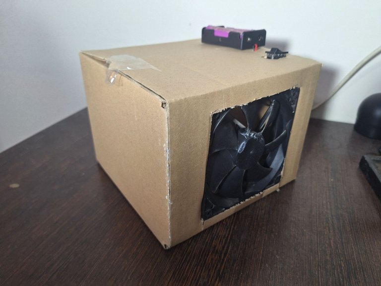
Using some recycled materials, I built my own fume extractor. Here are the key features:
- Filter Placement: I’ll soon be adding professional-grade filters to ensure maximum purification of the soldering fumes.
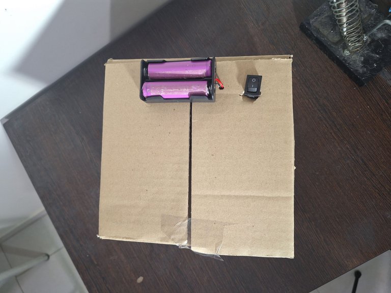
- Battery Configuration: I mounted the recycled batteries on top of the enclosure, making them easy to replace or upgrade.
- Future Development: Adding a lithium battery charging circuit will allow the device to charge via an adapter. This will not only charge the batteries but also power the device simultaneously.
- Convenience: A switch at the top of the box enables quick on/off control.
In an upcoming post, I’ll share a detailed video tutorial on how to build this DIY fume extractor, complete with step-by-step guidance on assembling the circuitry and sourcing the right filters.
2. Powering the SIM800L Module with Recycled Batteries
The second project involved using these recycled batteries to power a SIM800L module—a versatile GSM module commonly used for IoT applications. Here’s how I approached it:
- Voltage Regulation:
- The raw output from the batteries was connected to a voltage step-down module (buck converter) to provide a stable supply suitable for the SIM800L module.
- Capacitor Integration:
- A 1000µF capacitor was added across the VCC and GND pins of the module. This capacitor helps stabilize the voltage, reducing noise and voltage spikes that could disrupt the module’s operation.
- Result:
- The setup is now capable of handling GSM communication with minimal interference, thanks to proper voltage regulation and stabilization.
This approach highlights the importance of understanding power requirements when working with sensitive electronic modules like the SIM800L.
![20250115_131409.mp4_snapshot_00.02_[2025.01.15_18.58.33].png](https://images.hive.blog/768x0/https://files.peakd.com/file/peakd-hive/hadif66/23vsSgq5sn94ha3SL7MiJ2cC93y72AGC4hjtBmGRgbn5Wozhq4WcwDuCghGgrsq2N61sm.jpg)
3. Repurposing a CMS-S76 Driver Module from a DVD Player
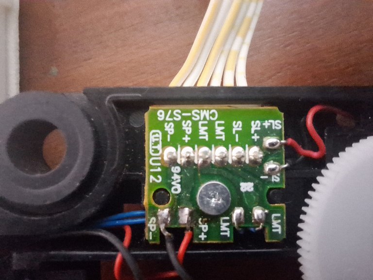
During a recent visit to an electronics scrap store, I stumbled upon a discarded DVD player. Among its components, I found a CMS-S76 motor driver module—a highly useful circuit for controlling DC motors.

Here’s what I discovered and how it can be utilized:
- Motor Control:
This driver module can control small 5V DC motors using PWM (Pulse Width Modulation) signals. PWM allows precise control over the motor’s speed and direction by varying the duty cycle of the signal. - Micro Switch Functionality:
The module also features two pins connected to a micro switch. This switch is commonly used in DVD players to detect whether the disc tray is open or closed. Based on the switch’s state, the driver module can automatically start or stop the motor.
![20250115_131010.mp4_snapshot_00.04_[2025.01.15_19.05.38].png](https://images.hive.blog/768x0/https://files.peakd.com/file/peakd-hive/hadif66/23x19TYVqEFG3YUujYbGRQrhYXdtzfhEAsYvbGwGHUFUGC8V8vpQWYkqdELc5sswtxgMm.jpg)
Technical Insights:
- PWM Basics:
PWM is a technique where the width of the "on" pulse in a signal is modulated while keeping the frequency constant. This effectively adjusts the motor's speed without wasting energy as heat, unlike resistive methods. - Applications:
This driver module can be repurposed for various projects, such as building an RC car or automated mechanisms. Its compact design and ability to interface with standard microcontrollers (e.g., ESP32 or Arduino) make it ideal for hobbyist use.
In upcoming posts, I’ll dive deeper into how this module works, how to connect it with a microcontroller, and how to write PWM code to control motors effectively.
ESP32 Arduino Code:
// Define LMT button pins
const int lmtPin1 = 15; // Replace with your ESP32 pin for LMT signal 1
const int lmtPin2 = 2;  // Replace with your ESP32 pin for LMT signal 2

// Define motor control pins
const int motorPin1 = 13; // SP+ pin for motor
const int motorPin2 = 14; // SP- pin for motor

// State variable to track if the button is pressed
volatile bool buttonPressed = false;

void IRAM_ATTR handleButtonPress() {
  // Interrupt handler to set the buttonPressed flag
  buttonPressed = true;
}

void setup() {
  // Initialize serial for debugging
  Serial.begin(115200);

  // Set LMT pins as input
  pinMode(lmtPin1, INPUT_PULLUP);
  pinMode(lmtPin2, INPUT_PULLUP);

  // Set motor control pins as output
  pinMode(motorPin1, OUTPUT);
  pinMode(motorPin2, OUTPUT);

  // Attach interrupt to the LMT button (use one pin since they're connected to the same button)
  attachInterrupt(digitalPinToInterrupt(lmtPin1), handleButtonPress, FALLING);

  Serial.println("Setup complete. Monitoring the LMT button...");
}

void loop() {
  // Check if the button has been pressed
  if (buttonPressed) {
    // Reset the flag
    buttonPressed = false;

    // Force stop all operations
    stopMotor();
    Serial.println("LMT Button pressed! Forcing motor stop!");

    // Optional: Add a delay to debounce the button
    delay(300); // Short debounce delay
  }

  // Other operations
  performMotorTask();
}

void stopMotor() {
  // Stop motor by setting both motor pins LOW
  digitalWrite(motorPin1, LOW);
  digitalWrite(motorPin2, LOW);
  Serial.println("Motor stopped.");
}

void performMotorTask() {
  // State variables to manage motor direction and timing
  static unsigned long lastUpdateTime = 0;
  static int motorState = 0; // 0: Stopped, 1: Forward, 2: Reverse
  unsigned long currentTime = millis();

  // Update motor state every 2 seconds (2000 ms)
  if (currentTime - lastUpdateTime >= 2000) {
    lastUpdateTime = currentTime;

    switch (motorState) {
      case 0: // Stopped
        Serial.println("Motor turning forward...");
        digitalWrite(motorPin1, HIGH); // Forward direction
        digitalWrite(motorPin2, LOW);
        motorState = 1; // Move to next state
        break;

      case 1: // Turning forward
        Serial.println("Motor stopped.");
        digitalWrite(motorPin1, LOW);
        digitalWrite(motorPin2, LOW); // Stop motor
        motorState = 2; // Move to next state
        break;

      case 2: // Turning reverse
        Serial.println("Motor turning reverse...");
        digitalWrite(motorPin1, LOW);
        digitalWrite(motorPin2, HIGH); // Reverse direction
        motorState = 0; // Loop back to stopped state
        break;
    }
  }
}
This code controls a DC motor using an ESP32 and incorporates a limit (LMT) button as an emergency stop mechanism. Here's a breakdown of its functionality:
1. Pin Definitions
- lmtPin1 and lmtPin2: These are inputs connected to the LMT button. They detect when the button is pressed.
- motorPin1 and motorPin2: These are outputs used to control the DC motor's direction and state (forward, reverse, or stop).
2. Global Variables
- buttonPressed: A volatile boolean flag that indicates if the LMT button has been pressed. Declared as volatile to ensure proper behavior in the interrupt context.
3. Interrupt Service Routine (ISR)
- handleButtonPress():
- An ISR triggered when the LMT button is pressed.
- Sets buttonPressed = true, signaling that the button was activated.
- Declared with IRAM_ATTR to ensure the ISR runs from the ESP32's instruction RAM for fast execution.
4. setup() Function
- Configures pin modes:
- LMT pins (lmtPin1 and lmtPin2): Set as input with pull-up resistors to detect button presses.
- Motor control pins (motorPin1 and motorPin2): Set as outputs to control the motor.
- Attaches an interrupt to lmtPin1:
- Triggered on the falling edge (when the button is pressed).
- Initializes the serial monitor for debugging.
5. loop() Function
- Continuously checks the buttonPressed flag:
- If true, it:
- Resets the flag to false.
- Calls stopMotor() to halt the motor immediately.
- Logs the button press to the serial monitor.
- Includes an optional debounce delay to prevent repeated triggers.
- If true, it:
- Calls performMotorTask() for motor control if the button hasn’t interrupted.
6. stopMotor() Function
- Stops the motor by setting both control pins (motorPin1 and motorPin2) to LOW.
- Logs the stop action to the serial monitor.
7. performMotorTask() Function
Implements a state machine to control the motor's behavior:
- States:
- 0 (Stopped): Stops the motor.
- 1 (Forward): Turns the motor forward by setting motorPin1 = HIGH and motorPin2 = LOW.
- 2 (Reverse): Reverses the motor direction by setting motorPin1 = LOW and motorPin2 = HIGH.
- States:
Transitions between states every 2 seconds using millis() for non-blocking timing.
Ensures the motor alternates between forward, stop, and reverse without interfering with the LMT button.
Key Features
- Interrupt-Driven Emergency Stop:
- The LMT button can force the motor to stop immediately, regardless of ongoing operations.
- The interrupt ensures rapid response without delays.
- Non-Blocking Motor Control:
- The use of millis() allows smooth motor state transitions without blocking other code (e.g., interrupt handling).
- Safe and Expandable:
- The modular design makes it easy to expand the code for additional functionalities like speed control using PWM.
Practical Applications
- Robotics: Emergency stop for motorized robots.
- DIY RC Cars: Controlled directional movement with a fail-safe mechanism.
- Automation Systems: Ensures safety by stopping operations when a limit switch or button is triggered.
Closing Thoughts
Repurposing electronic waste not only saves money but also contributes to a sustainable environment. From making safer workspaces to powering IoT modules and controlling motors, these projects demonstrate the versatility of recycled components.
Stay tuned for more updates as I expand on these ideas and share detailed tutorials for each project. Thank you for joining me on this journey!
Feel free to share your thoughts or ask questions in the comments section.

