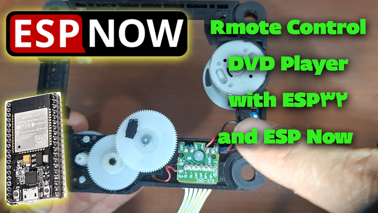
Controlling the CMS-S76 Module with Two ESP32s and the ESP-NOW Protocol
Hello friends! I'm a hobbyist and programmer. Today, I was rummaging through some old junk and discarded items in the storage when I stumbled upon a part from an old DVD player. Since I was looking for a DC motor and driver for my remote-controlled robot project, I decided to kick off my work using these parts. So, if you're interested in these topics, this post is for you!

In the ever-evolving world of the Internet of Things (IoT), efficient wireless communication protocols play a critical role in creating seamless and responsive systems. One such powerful protocol is ESP-NOW, which enables fast, peer-to-peer communication without the need for Wi-Fi or Bluetooth. In this guide, we’ll explore how to control the highly capable CMS-S76 module using two ESP32 microcontrollers and the ESP-NOW protocol.
Before getting started here is a short video on my youtube channel of how the whole thing works:
https://www.youtube.com/shorts/7_Do0khbZTQ
And here I explained everything in details(in Farsi language):
Understanding the CMS-S76
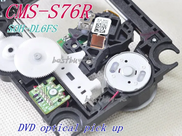
The CMS-S76 has several input and output pins. Key inputs include SP (positive and negative), LMT (limit switch), and SL (positive and negative). The SL inputs connect to the DC motors (typically around 5-12V), while the LMT pins are for connecting limit switches. These switches, when activated, can stop the motors. The module also acts as a driver, allowing for motor speed control using PWM (Pulse Width Modulation).
![0117(1).mp4_snapshotsss_00.37_[2025.01.17_04.19.24].jpg](https://images.hive.blog/768x0/https://files.peakd.com/file/peakd-hive/hadif66/23vsJHzG6TBJWfQNyypfvxreMn6hYq8XngYNGKXZ1Z5k3ggES6rf94U3LUiF7p9GpTery.jpg)

Image Source : aliexpress
Project 1: Basic Motor Control with an ESP32
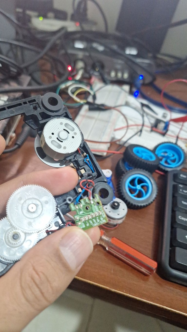
For the first project, I used an ESP32 microcontroller to control the CMS-S76. The setup involved:
- Connecting the SL inputs of the module to pins 13 and 14 of the ESP32 (configured as outputs).
- Connecting the LM inputs to pins 2 and 15 of the ESP32 (configured as inputs).
The code was designed to make the motor rotate forward for a few seconds, then reverse. When the limit switch is pressed, the motor stops. Releasing the switch allows the motor to resume its rotation. This demonstrates a simple yet effective way to control the motor using the limit switch functionality.
![0117(1).mp4_snapshot_04.40_[2025.01.17_04.21.54].jpg](https://images.hive.blog/768x0/https://files.peakd.com/file/peakd-hive/hadif66/23tvegWFqAetwph1rzPtopaDZAAbfFNv8t5mjuNxf66MdfXF4v5r5Zrt972tfWhjgS2zB.jpg)
And here is the code for this part:
// Define LMT button pins
const int lmtPin1 = 15; // Replace with your ESP32 pin for LMT signal 1
const int lmtPin2 = 2;  // Replace with your ESP32 pin for LMT signal 2

// Define motor control pins
const int motorPin1 = 13; // SP+ pin for motor
const int motorPin2 = 14; // SP- pin for motor

// State variable to track if the button is pressed
volatile bool buttonPressed = false;

void IRAM_ATTR handleButtonPress() {
  // Interrupt handler to set the buttonPressed flag
  buttonPressed = true;
}

void setup() {
  // Initialize serial for debugging
  Serial.begin(115200);

  // Set LMT pins as input
  pinMode(lmtPin1, INPUT_PULLUP);
  pinMode(lmtPin2, INPUT_PULLUP);

  // Set motor control pins as output
  pinMode(motorPin1, OUTPUT);
  pinMode(motorPin2, OUTPUT);

  // Attach interrupt to the LMT button (use one pin since they're connected to the same button)
  attachInterrupt(digitalPinToInterrupt(lmtPin1), handleButtonPress, FALLING);

  Serial.println("Setup complete. Monitoring the LMT button...");
}

void loop() {
  // Check if the button has been pressed
  if (buttonPressed) {
    // Reset the flag
    buttonPressed = false;

    // Force stop all operations
    stopMotor();
    Serial.println("LMT Button pressed! Forcing motor stop!");

    // Optional: Add a delay to debounce the button
    delay(300); // Short debounce delay
  }

  // Other operations
  performMotorTask();
}

void stopMotor() {
  // Stop motor by setting both motor pins LOW
  digitalWrite(motorPin1, LOW);
  digitalWrite(motorPin2, LOW);
  Serial.println("Motor stopped.");
}

void performMotorTask() {
  // State variables to manage motor direction and timing
  static unsigned long lastUpdateTime = 0;
  static int motorState = 0; // 0: Stopped, 1: Forward, 2: Reverse
  unsigned long currentTime = millis();

  // Update motor state every 2 seconds (2000 ms)
  if (currentTime - lastUpdateTime >= 2000) {
    lastUpdateTime = currentTime;

    switch (motorState) {
      case 0: // Stopped
        Serial.println("Motor turning forward...");
        digitalWrite(motorPin1, HIGH); // Forward direction
        digitalWrite(motorPin2, LOW);
        motorState = 1; // Move to next state
        break;

      case 1: // Turning forward
        Serial.println("Motor stopped.");
        digitalWrite(motorPin1, LOW);
        digitalWrite(motorPin2, LOW); // Stop motor
        motorState = 2; // Move to next state
        break;

      case 2: // Turning reverse
        Serial.println("Motor turning reverse...");
        digitalWrite(motorPin1, LOW);
        digitalWrite(motorPin2, HIGH); // Reverse direction
        motorState = 0; // Loop back to stopped state
        break;
    }
  }
}
Project 2: Wireless Remote Control with ESP32s and ESP-NOW
The second project involved wireless remote control using two ESP32 microcontrollers and the ESP-NOW protocol. This setup allowed for remote control of the motor.
- One ESP32 acted as the master (remote control).
- The other ESP32 acted as the slave, connected to the CMS-S76 module.
The ESP-NOW protocol was used for wireless communication between the two ESP32s. Pressing buttons on the master ESP32 sent signals to the slave ESP32, which then controlled the motor's direction. This effectively created a wireless remote control system.
![0117(1).mp4_snapshot_06.10_[2025.01.17_04.29.43].jpg](https://images.hive.blog/768x0/https://files.peakd.com/file/peakd-hive/hadif66/23xAVtFCu13qc2TRy6iTLMe3Jc4gYWW8AsuZzWE2QaLLZVKbTab4xjUAJsb5aBSoyVmAU.jpg)
ESP-NOW Details
ESP-NOW operates on the 2.4GHz frequency band, similar to Wi-Fi, but is a connectionless protocol, which allows for faster communication and lower latency compared to traditional Wi-Fi connections. In this project, one ESP32 was designated as the master and the other as the slave. The master ESP32 sent commands to the slave, which then controlled the motor connected to the CMS-S76 module.
Alternative Wireless Communication Methods and Considerations
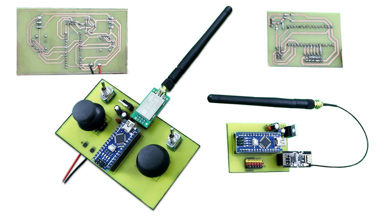
While ESP-NOW was used in this project, other wireless communication methods are available, such as using NRF24L01 transceivers. However, these often involve additional modules and costs. The choice of wireless communication method depends on factors like cost and power consumption. ESP-NOW, while convenient and readily available on ESP32s, can consume more power compared to some other options.

Image Source: rcpano.net
Conclusion
The CMS-S76 is a versatile motor driver module that can be easily integrated with various microcontrollers for a wide array of projects. From simple limit switch control to more complex wireless remote control systems, the possibilities are numerous. This post demonstrated two such projects, showcasing the module’s capabilities and providing a starting point for further exploration.
Key takeaways:
- The CMS-S76 can control both DC and spindle motors.
- Limit switches can be used to stop the motors.
- PWM can be used for speed control.
- ESP-NOW is a convenient protocol for wireless control with ESP32s.
- Consider cost and power consumption when choosing a wireless communication method.
In the future post and youtube videos I will make RC robot on wheels using the DC motors and the driver that I took out of the DVD player.

I hope this post has been informative and helpful. Feel free to leave any questions or comments below.
!DIYSTATS