Para alguien es una simple esponja, para mi es un modelo didáctico para explicar la flexión en vigas (Esp-Eng)
Versión en Español
Amigos de la comunidad científica de HIVE, un honor abordar estos temas de la ingeniería estructural con ese toque didáctico para que profesionales, estudiantes y público en general comprenda lo que se desea exponer. En esta ocasión abordaremos el esfuerzo principal al que se encuentran sometidas las vigas, esos elementos horizontales de las estructuras, que en el caso específico de las estructuras tipo pórticos conectan los elementos columnas (elementos verticales), y este esfuerzo principal al que están sometidas es la Flexión.

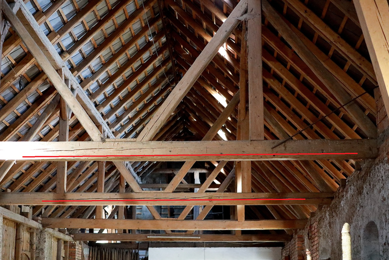
Las vigas (resaltadas con las líneas de color rojo de la imagen) son elemento estructurales sometidos a esfuerzos de flexión, siendo la flexión un esfuerzo caracterizado porque una parte del elemento se comprime y la otra parte se tracciona, entendiendo cada uno de estas consecuencias como acortamientos y alargamientos respectivamente de las fibras que conforman el elemento estructural en cuestión.
@eliaschess333 ¿qué origina estas consecuencias?
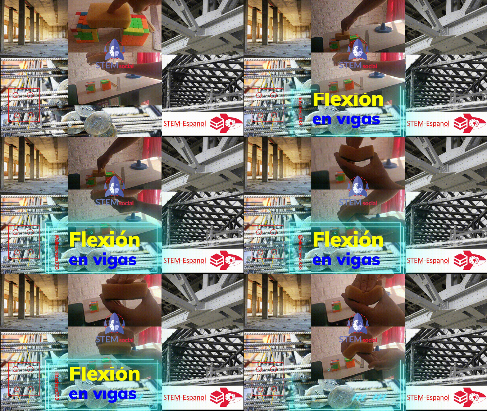
Las cargas, siendo las tradicionales las cargas gravitacionales resultado del peso propio de la estructura, recordemos que las vigas reciben las cargas gravitacionales que la losa transmite, y estas cargas gravitacionales pueden ser permanentes (peso propio de la estructura) y las cargas variables en esencia productos del uso de la edificación. En la siguiente imagen animada intento simular con mi mano estas cargas:
Acá se ve como la parte inferior de la esponja se alarga y la parte superior se acorta, viendo así a través de este modelo didáctico representado por una simple esponja, estos esfuerzos de flexión en plena acción. Ahora bien, en un elemento de concreto armado como el de la imagen inicial tenemos la interacción de dos materiales concreto y acero. El concreto es el encargado de soportar los esfuerzos de compresión y el acero los de tracción.
@eliaschess333 ¿Significa entonces que con colocar acero en la parte inferior es suficiente?
Fuente
Este acero que va en sentido longitudinal, las normas estructurales exigen un mínimo en la parte que está a compresión, y la razón practica es para los efectos constructivos en el proceso de colocación del acero transversal. Y también porque la flexión puede ser en sentido contrario, cuando el elemento lo vemos desde el enfoque de la ingeniería sismorresistente, donde puede ocurrir producto de la acción sísmica en la estructura una inversión en los esfuerzos que originan la flexión, esfuerzos que de un modo didáctico se intentan lustrar en esta imagen animada:

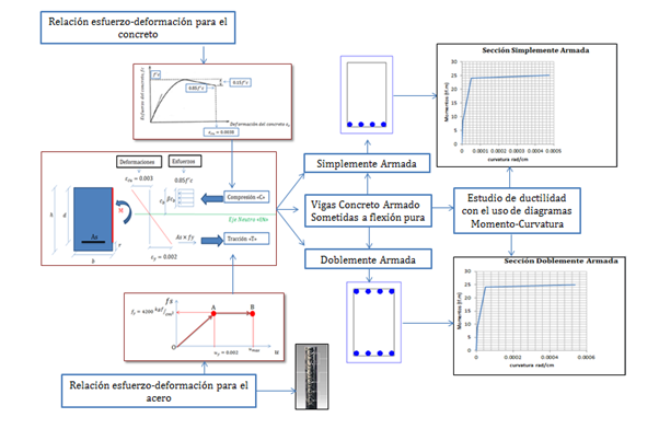
Entonces acá es necesario que la viga de concreto armado esté reforzada tanto en la parte inferior como superior, por ese en el campo del concreto armado se habla de secciones de viga doblemente armadas. Este es un tema fascinante de la ingeniería estructural, en esta publicación me limito a ilustrar el concepto de la flexión, encargado de ser resistido por el acero longitudinal. Si quieres tener una visión más estricta del tema sobre el comportamiento de las vigas ante cargas y sus mecanismos de falla te invito a que disfrutes de esta publicación, preparada unos cuantos años atrás, donde abordo estas ideas con un enfoque más riguroso desde el punto de vista de las matemáticas y la ingeniería sismorresistente.
Y finalmente vale destacar que estas ideas relacionadas al concepto de los esfuerzos a flexión, se extienden a las vigas construidas de cualquier material ya sean de acero, madera como las que se muestran en las siguientes imágenes:
Espero este concepto de flexión te haya llamado la atención y hayas podido comprender la esencia del significado del mismo, así como los elementos de una estructura que típicamente están sometidos a estos esfuerzo como lo son las vigas. Acotando que en el caso de las vigas puedes surgir esfuerzos de corte, y en el caso específico de las vigas de concreto armado, es el acero transversal el encargado de resistir tales esfuerzos, lo cual abordaremos en futuras publicaciones. Hasta una próxima oportunidad mi gente linda. Escribió para ustedes:
Notas de Importancia:
Las imágenes animadas fueron editadas con la herramienta Filmora 11
El traductor empleado para la versión en Inglés fue DeepL
Referencias Bibliográficas
Andrew Pytel y Ferdinand Singer. Resistencia de Materiales-Introducción a la Mecánica de Sólidos. Cuarta Edición. 1994
English Version
Friends of the scientific community of HIVE, it is an honor to address these topics of structural engineering with that didactic touch so that professionals, students and the general public can understand what we want to expose. On this occasion we will address the main stress to which beams are subjected, those horizontal elements of structures, which in the specific case of portal frame structures connect the column elements (vertical elements), and this main stress to which they are subjected is bending.

Beams (highlighted with the red lines in the image) are structural elements subjected to bending stresses, bending being a stress characterized by one part of the element being compressed and the other part being tractioned, each of these consequences being understood as shortening and lengthening, respectively, of the fibers that make up the structural element in question.
@eliaschess333 what causes these consequences?
The loads, being the traditional ones the gravity loads resulting from the own weight of the structure, let's remember that the beams receive the gravity loads that the slab transmits, and these gravity loads can be permanent (own weight of the structure) and the variable loads in essence products of the use of the building. In the following animated image I try to simulate these loads with my hand:

Here we see how the lower part of the sponge is elongated and the upper part is shortened, thus seeing through this didactic model represented by a simple sponge, these bending stresses in full action. Now, in a reinforced concrete element such as the one in the initial image, we have the interaction of two materials, concrete and steel. The concrete is in charge of supporting the compressive stresses and the steel the tensile stresses.
@eliaschess333 Does it mean then that putting steel on the bottom is enough?
Source This steel that goes in longitudinal direction, the structural norms demand a minimum in the part that is in compression, and the practical reason is for the constructive effects in the process of placing the transversal steel. And also because the bending can be in the opposite direction, when we see the element from the seismic-resistant engineering approach, where a product of the seismic action can occur in the structure an inversion in the efforts that originate the bending, efforts that in a didactic way we try to show in this animated image:
So here it is necessary that the reinforced concrete beam is reinforced both at the bottom and at the top, that is why in the field of reinforced concrete we speak of double reinforced beam sections. This is a fascinating topic of structural engineering, in this publication I limit myself to illustrate the concept of bending, which is resisted by the longitudinal steel. If you want to have a stricter view on the behavior of beams under loads and their failure mechanisms, I invite you to enjoy this publication, prepared a few years ago, where I address these ideas with a more rigorous approach from the point of view of mathematics and earthquake-resistant engineering.
And finally, it is worth noting that these ideas related to the concept of bending stresses extend to beams made of any material, whether steel or wood, such as those shown in the following images:
I hope this concept of bending has caught your attention and you have been able to understand the essence of its meaning, as well as the elements of a structure that are typically subjected to these stresses, such as beams. It should be noted that in the case of beams, shear stresses can arise, and in the specific case of reinforced concrete beams, it is the transverse steel that is in charge of resisting such stresses, which we will address in future publications. Until next time my beautiful people. Written for you:
Important Notes:
The translator used for the English version was DeepL
Bibliographical References
Andrew Pytel and Ferdinand Singer. Strength of Materials-Introduction to Solid Mechanics. Fourth Edition. 1994
Posted Using InLeo Alpha


Thanks for your contribution to the STEMsocial community. Feel free to join us on discord to get to know the rest of us!
Please consider delegating to the @stemsocial account (85% of the curation rewards are returned).
You may also include @stemsocial as a beneficiary of the rewards of this post to get a stronger support.
Thanks for the support!!