Temperature transmitter with dual calibration adjustment EN/ES
Once given the articles Reading and writing EEPROM memory on PIC16F877A ENG/ESP and Circuit for Data Acquisition from a PT100 EN/ES we can use all the acquired knowledge and add the previous ones related to the use of microcontrollers to design a temperature transmitter with dual calibration adjustment.
One of the most difficult variables to measure and control accurately is the temperature, in this article we will take advantage of the proposed circuit for data acquisition from a PT100 to bring that data to a microcontroller and seek to carry out a calibration that gives us the data as accurately as possible.
Una vez dados los artículos Reading and writing EEPROM memory on PIC16F877A ENG/ESP y Circuit for Data Acquisition from a PT100 EN/ES podemos usar todos los conocimientos adquiridos y sumarles los anteriores relacionados al uso de microcontroladores para diseñar un transmisor de temperatura con ajuste de calibración dual.
Una de las variables más difíciles de medir y controlar con precisión es la temperatura, en este artículo vamos a aprovechar el circuito propuesto para la adquisición de datos desde una PT100 para llevar esos datos a un microcontrolador y buscar llevar a cabo una calibración que nos entregue los datos con la mayor precisión posible.
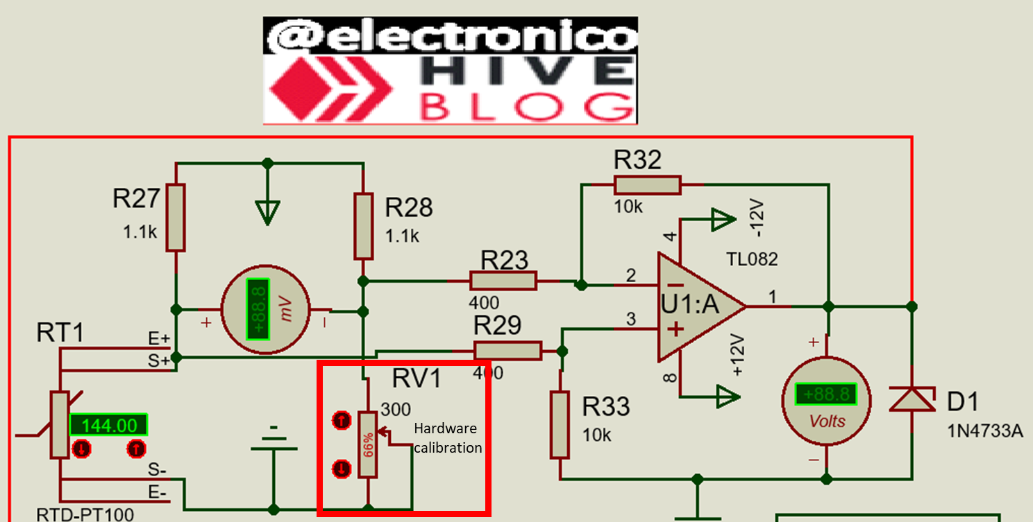
In the mentioned circuit we placed a potentiometer as a mirror of the PT100 in the Wheatstone bridge, this potentiometer is used to adjust the values and correct errors. While it is true that calculations were made for these circuits, it is also true that in reality the resistive values are not as accurate as one would like.
It must be taken into account that the variation of the PT100 for each degree Celsius is a few ohms and this can make it frustrating to achieve a perfect calibration. Therefore, today we propose two adjustment points and we can see the first one at a glance.
En el circuito mencionado colocamos un potenciómetro como espejo de la PT100 en el puente de Wheatstone, este potenciómetro se utiliza para ajustar los valores y corregir errores. Si bien es cierto que se hicieron cálculos para estos circuitos también lo es que en la realidad los valores resistivos no son tan precisos como uno querría.
Hay que tomar en cuenta que la variación de la PT100 por cada grado centígrado es de unos pocos ohmios y esto puede hacer frustrante lograr una calibración perfecta. Por ello hoy se proponen dos puntos de ajuste y de una vez podemos ver el primero.
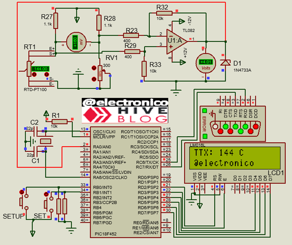
Since we need to evaluate the effectiveness of each calibration and our circuit, we will use a PIC18F452 microcontroller to receive the data coming from the operational amplifier, this data will be processed by an ADC and the conversion will be made to the corresponding temperature value.
An LCD screen will be in charge of showing us the read values, a UART connector to transmit them to where they are needed (that's why I called it temperature transmitter), we can also see the buttons called SETUP and SET, the SETUP button activates the RB0 interrupt to configure a software calibration and SET allows us to enter the values that determine the measurement range (min and max).
Before calibrating and checking the calibrations let's understand how the program works:
Taking into account that an ADC, character string, serial transmission, and display pins among other connections will be used the configuration lines are set as follows:
Ya que necesitamos evaluar la efectividad de cada calibración y de nuestro circuito, vamos a usar un microcontrolador PIC18F452 para recibir lo datos provenientes del amplificador operacional, estos datos se van a procesar por un ADC y se hará la conversión al valor de temperatura correspondiente.
Una pantalla LCD se encargará de mostrarnos los valores leídos, un conector UART de transmitirlos a donde sea necesarios (por eso lo llamé transmisor de temperatura), también podemos ver los pulsadores llamados SETUP y SET, el pulsador SETUP activa la interrupción por RB0 para configurar una calibración por software y SET permite ingresar los valores que determinan el rango de medición (min y max).
Antes de calibrar y comprobar las calibraciones vamos a comprender el funcionamiento del programa:
Tomando en cuenta que se usará un ADC, cadena de caracteres, transmisión serial, y pines para la pantalla entre otras conexiones las líneas de configuración se establecen de la siguiente forma:
#include <18f452.h>
#device PASS_STRINGS = IN_RAM
#device ADC = 8
#fuses HS,NOWDT,NOPROTECT,NOLVP,NOPUT,NODEBUG
#use delay(clock=20M)
#use RS232(BAUD=9600, BITS=8, PARITY=N, XMIT=PIN_C6, RCV=PIN_C7)
#use standard_io(A)
#use fast_io(B)
#use standard_io(C)
#use standard_io(D)
It is very important to highlight that we are using an 8bit resolution for the ADC (#device ADC=8) instead of the 10bit resolution that we usually use, the reason for this is because we are going to store ADC values in the EEPROM memory and if we remember the EEPROM memory registers are 8Bits, using a resolution of 10Bits would require 2 registers in the EEPROM to store a data apart from the arrays to do this, in order to simplify things we use a resolution of 8Bits so that the data can be stored without problems in a single register.
Now we configure the connections for the LCD and the SET button (the SETUP is not configured because it is directly associated to the RB0 interrupt) we create the min, max, setup, ttx, adc1 and adc2 variables that will be useful in the software calibration.
Es de suma importancia resaltar que estamos usando una resolución de 8bits para el ADC (#device ADC=8) en lugar de la resolución de 10 que habitualmente usamos, la razón de esto es porque vamos a almacenar valores del ADC en la memoria EEPROM y si recordamos los registros de la memoria EEPROM son de 8Bits, usar una resolución de 10Bits haría que se necesitasen 2 registros en la EEPROM para almacenar un dato a parte de los arreglos para hacer esto, con la finalidad de simplificar las cosas usamos una resolución de 8Bits para que el dato se pueda almacenar sin problemas en un solo registro.
Ahora configuramos las conexiones para la LCD y el pulsador SET (el SETUP no se configura porque está directamente asociado a la interrupción RB0) se crean las variables min, max, setup, ttx, adc1 y adc2 que serán útiles en la calibración por software.
#define set       PIN_B1
#define LCD_DB4   PIN_D4
#define LCD_DB5   PIN_D5
#define LCD_DB6   PIN_D6
#define LCD_DB7   PIN_D7
#define LCD_RS    PIN_D2
#define LCD_E     PIN_D3
#include <LCD_16X2.c

int min, max, setup;
long adc1, adc2, ttx;
We want the software calibration to be accessible whenever the operator wants it, that is why we have placed a SETUP button that takes the program to this routine through an interruption, once the button is pressed the software calibration menu is entered, this will be configured as follows:
Queremos que se pueda acceder a la calibración por software siempre que el operador lo desee, por eso se ha colocado un pulsador SETUP que lleva al programa a esta rutina mediante una interrupción, una vez que el pulsador es accionado se entra en el menú de calibración por software, este quedará configurado como sigue:
#INT_EXT
void interruption_RB0()
{
  setup = 1;
  while(setup == 1)
  {
   set_adc_channel(0);
   delay_us(20);
   adc1=read_adc();
   delay_ms(100);
   lcd_clear();
   lcd_gotoxy(1,1);
   printf(lcd_putc, "Push set to 0");
   lcd_gotoxy(1,2);
   printf(lcd_putc, "ADC VALUE: %lu", adc1);
   delay_ms(500);
   if(input(set)== 1)
   {
    set_adc_channel(0);
    delay_us(20);
    adc1 = read_adc();
    write_eeprom(1, adc1);
    delay_ms(100);
    setup=2;
   }
  }

  while(setup == 2)
  {
   set_adc_channel(0);
   delay_us(20);
   adc2=read_adc();
   lcd_clear();
   lcd_gotoxy(1,1);
   printf(lcd_putc, "Push set to 150");
   lcd_gotoxy(1,2);
   printf(lcd_putc, "ADC VALUE: %lu", adc2);
   delay_ms(500);
   if(input(set) == 1)
   {
    set_adc_channel(0);
    delay_us(20);
    adc2 = read_adc();
    write_eeprom(2, adc2);
    delay_ms(100);
    setup=0;
   }
  }
}
In this code the user is shown the value being read from the ADC and is prompted to press when he/she considers the value read to be the desired 0, the operator can use a calibration instrument, add a controlled temperature or use a potentiometer to bring the ADC to the desired value and then press SET to make that value the 0 setting.
Subsequently the same is done for the maximum value which we have set to 150°C and both values (min and max) are stored in EEPROM memory for later use.
In the main program we configure the ADC, the RB0 interrupt, port B as output and initialize the LCD.
En este código se le muestra al usuario el valor que se está leyendo en el ADC y se le pide que pulse cuando considere que el valor leído es el 0 deseado, el operador puede usar un instrumento de calibración, añadir una temperatura controlada o usar un potenciómetro para llevar el ADC al valor deseado y entonces pulsar SET para que ese valor sea el ajuste de 0.
Posteriormente se hace lo mismo para el valor máximo que hemos establecido en 150°C y ambos valores (min y max) se almacenan en la memoria EEPROM para ser usados posteriormente.
En el programa principal se configura el ADC, la interrupción RB0, el puerto B como salida y se inicializa la LCD.
void main()
{

 set_tris_b(0xFF);
 enable_interrupts(INT_EXT);
 ext_int_edge(L_TO_H);
 enable_interrupts(GLOBAL);
 setup_adc_ports(AN0);
 setup_adc(adc_clock_internal);
 lcd_init();
Inside the while loop the first thing we do is to load the min and max variables with the values that have been saved in the EEPROM during the software calibration.
Dentro del bucle while lo primero que hacemos es cargar las variables min y max con los valores que se han guardado en la EEPROM durante la calibración por software.
while(true)
 {
  min = read_eeprom(1);
  max = read_eeprom(2);
Considering that the calibration is dual and that the eeprom has no stored values at the first power-up, it is configured by means of a conditional if that if the value in the max variable is less than or equal to 10, the hardware calibration is operated with the understanding that a value less than 10 at this point will appear if the software calibration has not been performed or if the calibration is wrong.
Then, if after performing the software calibration you wish to work with the hardware calibration, you only have to recalibrate by setting the max value below 10.
Considerando que la calibración es dual y que en el primer encendido la eeprom no tiene valores almacenados se configura mediante un condicional if que si el valor en la variable max es menor o igual a 10 se opera con la calibración por hardware entendiendo que un valor menor a 10 en este punto aparecerá si no se ha hecho la calibración por software o si la calibración está mal.
Entonces, si luego de hacer la calibración por software se desea trabajar con la calibración por hardware solo hay que volver a calibrar colocando el valor max por debajo de 10.
if(max <= 10)
 {
 set_adc_channel(0);
 delay_us(20);
 ttx = map(read_adc(), 0, 255, 0, 150);
 }
It is important to note that for 255 the maximum of 150° has been set, this means that in a hardware calibration the output of the differential amplifier should be 5V when the temperature is 150°.
If the max value is greater than 10 the system understands that a software calibration has been performed and will operate with these values. To do this it will convert the min and max values to the range 0 and 150.
Es importante notar que para 255 se ha establecido el máximo de 150°, esto significa que en una calibración por hardware la salida del amplificador diferencial debe ser 5V cuando la temperatura sea 150°
Si el valor max es mayor que 10 el sistema entiende que se ha efectuado una calibración por software y operará con estos valores. Para ello convertirá los valores min y max en el rango 0 y 150.
if(max > 10)
 {
  set_adc_channel(0);
  delay_us(20);
  ttx = map(read_adc(), min, max, 0, 150);
 }
Finally, the data read for the temperature variable is taken and displayed on the LCD and sent to the serial port using the printf command.
Finalmente se toman los datos leídos para la variable temperatura y se muestran en la LCD, además se envían al puerto serial mediante el comando printf.
lcd_clear();
 lcd_gotoxy(1,1);
 printf(lcd_putc, "TTX: %lu C", ttx);
 lcd_gotoxy(1,2);
 printf(lcd_putc, "@electronico");
 printf("%lu \r\n", ttx);
 delay_ms(300);
 }
}
Now let's try the hardware calibration, for this we will bring the PT100 to 150°C and by means of the adjustment potentiometer we will try to obtain 5V at the output of the operational amplifier or 150° on the display.
After calibration we will lower the value of the PT100 and compare the value given by the PT100 with the measured value to evaluate the accuracy of the hardware calibration. Out of 150 75% would be 115, 50% 75 and 25% 38, finally we take it to 0 by comparing these values.
Ahora intentemos la calibración por hardware, para ello llevaremos la PT100 a 150°C y mediante el potenciómetro de ajuste intentaremos obtener 5V en la salida del amplificador operacional o 150° en pantalla.
Luego de la calibración se bajará el valor de la PT100 y compararemos el valor dado por la PT100 con el valor medido para evaluar la precisión de la calibración por hardware. De 150 el 75% sería 115, el 50% 75 y el 25% 38, finalmente lo llevamos al 0 comparando estos valores.
You can notice a deviation that becomes larger as the variable approaches 0, this may be due to the fact that the results depend on resistive values and a small error is also amplified along with the value of the variable.
It is likely that in reality this deviation is not so large, however we will proceed with the software calibration and later with the test to evaluate the difference between one mode and another.
Se puede notar una desviación que se hace más grande a medida que la variable se acerca al 0, esto se puede deber a que los resultados dependen de valores resistivos y un pequeño error es también amplificado junto con el valor de la variable.
Es probable que en la realidad esta desviación no sea tan grande, sin embargo vamos a proceder con la calibración por software y posteriormente con la prueba para evaluar la diferencia entre un modo y otro.
Finally, we evaluate the measurements with the software calibration.
Para terminar hacemos la evaluación de las mediciones con la calibración hecha por software.

As we can notice the hardware calibration presents a better accuracy, this is because you can adjust the range in two points (0-150) and the intermediate values are taken to equivalences. In the case of hardware calibration it is only possible to adjust the range to the minimum or maximum value, and it is easier for someone to move the potentiometer and calibrate it by mistake.
Although the arbitrarily chosen range 0-150 will work for any other range, it can also be carried in percentage terms (0-100%) and could be adapted to any process by software calibration only.
It also demonstrates the usefulness of using the EEPROM memory since thanks to store the data in this memory it will not be necessary to configure the settings at each power on but the calibration data will remain even when the equipment is turned off.
That's all, I hope you found this article useful and I look forward to hearing from you in the comments.
Como podemos notar la calibración por hardware presenta una mejor precisión, esto es así porque se puede ajustar el rango en dos puntos (0-150) y los valores intermedios se llevan a equivalencias. En el caso de la calibración por hardware solo se puede ajustar al valor mínimo o máximo, además es más fácil que alguien mueva el potenciómetro y lo descalibre por error.
Aunque se ha elegido arbitrariamente el rango 0-150 funcionará para cualquier otro, también se puede llevar en términos porcentuales (0-100%) y se podría adaptar a cualquier proceso únicamente haciendo la calibración por software.
Queda demostrado además la utilidad de usar la memoria EEPROM ya que gracias a almacenar los datos en esta memoria no hará falta configurar los ajustes en cada encendido sino que los datos de calibración permanecerán incluso cuando el equipo se apague.
Esto es todo, espero que este artículo te haya sido de utilidad y quedo atento a los comentarios.
If you want to give an extra boost to the blog with a donation you can send it to the addresses:
Si quieres darle un impulso extra al blog con una donación puedes enviarla a las direcciones:
BEP-20: 0x5Aee5e3e3ED3203e77eF0d8Bb3E3a420E5229Ce0
ERC-20: 0x5Aee5e3e3ED3203e77eF0d8Bb3E3a420E5229Ce0
Arbitrum One: 0x5Aee5e3e3ED3203e77eF0d8Bb3E3a420E5229Ce0
Polygon: 0x5Aee5e3e3ED3203e77eF0d8Bb3E3a420E5229Ce0
Avalanche: 0x5Aee5e3e3ED3203e77eF0d8Bb3E3a420E5229Ce0
Gracias palomita linda. Que Dios te bendiga y multiplique!!!
Thanks for your contribution to the STEMsocial community. Feel free to join us on discord to get to know the rest of us!
Please consider delegating to the @stemsocial account (85% of the curation rewards are returned).
Thanks for including @stemsocial as a beneficiary, which gives you stronger support.
Congratulations @electronico! You have completed the following achievement on the Hive blockchain And have been rewarded with New badge(s)
Your next target is to reach 19000 upvotes.
You can view your badges on your board and compare yourself to others in the Ranking
If you no longer want to receive notifications, reply to this comment with the word
STOPCheck out our last posts: