Single polarity non-inverting amplifier EN/ES
If you have noticed, so far every time we have worked in the design of electronic circuits with operational amplifiers have been used two voltage sources for powering them.
Someone with little knowledge and a lot of curiosity may wonder why two sources are used and not only one, in this article we will explain this topic, also we will present and explain the circuit of the following image which is a configuration to amplify using a single source.
Si lo has notado, hasta ahora cada vez que hemos trabajo en el diseño de circuitos electrónicos con amplificadores operacionales se han usado dos fuentes de voltaje para la alimentación de los mismos.
Alguien con pocos conocimientos y mucha curiosidad tal vez puede preguntarse por qué se usan dos fuentes y no solo una, en este artículo se explicará este tema, además se presenta y explica el circuito de la siguiente imagen que es una configuración para amplificar usando una sola fuente.

Before addressing the circuit of the previous image we will explain why the need to use two voltage sources.
An electronic signal is a magnitude that varies over time, among the values that can take there is the possibility that includes negative values, the essence of amplifying a signal increase its output values against the input at the same instant of time.
This increase must be in the same direction, if the value is negative the increase must be in the same direction. The voltages used by an amplifier to produce an output signal with gain are subject to the values with which it is fed, it will never offer gains whose output is higher than the supply voltage, and if this is the case a saturation and clipping of the signal (loss) will occur.
A power supply can only be positive or negative with respect to another point but not both directions at the same time. Therefore two sources are used, one to produce the positive side of the amplified signal and another to produce the negative.
Antes de abordar el circuito de la imagen anterior vamos a explicar el por qué la necesidad de usar dos fuentes de voltaje.
Una señal electrónica es una magnitud que varía en el tiempo, entre los valores que puede tomar existe la posibilidad que incluya valores negativos, la esencia de amplificar una señal aumentar sus valores de salida frente a la entrada en el mismo instante de tiempo.
Este aumento debe ser en la misma dirección, si el valor es negativo el aumento debe ser en la misma dirección. Los voltajes que usa un amplificador para producir una señal de salida con ganancia están sujetos a los valores con que es alimentado, nunca ofrecerá ganancias cuya salida sea superior al voltaje de alimentación, y si se da el caso ocurrirá una saturación y recorte de la señal (perdida).
Una fuente de alimentación solo puede ser positivo o negativa respecto a otro punto pero no ambas direcciones a la vez. Por eso se usan dos fuentes, una para producir el lado positivo de la señal amplificada y otra para producir el negativo.

If we know that our signal will be only positive or only negative we can use only one source, the corresponding one and connect the other power supply terminal to ground. But using two power supplies is impractical, if the power supplies are professional they require double the investment and if we decide to manufacture them double the number of components.
One of the things I like about electronics is that if you have enough creativity you can find practical solutions to this kind of problems.
The circuit shown in the first image takes advantage of the behavior of the current when we add an alternating current to a direct current to eliminate the need for a negative source.
Both voltages are added at all points, the result is that we will have all the oscillation of the signal in the positive quadrant thanks to the addition of a positive DC voltage, then this DC component can be decoupled with a capacitor to obtain the amplified signal with its two peaks (negative and positive). Let's put a pair of oscilloscope to observe this detail.
Si sabemos que nuestra señal sera solo positiva o solo negativa podemos usar solo una fuente, la que corresponda y el otro terminal de alimentación conectarlo a tierra. Pero usar dos fuentes es algo poco práctico, si las fuentes son profesionales se requiere el doble de inversión y si decidimos fabricarlas el doble de componentes.
Una de las cosas que me gusta de la electrónica es que si tienes suficiente creatividad puedes encontrar soluciones prácticas a este tipo de problemas.
El circuito mostrado en la primera imagen aprovecha el comportamiento de la corriente cuando sumamos una corriente alterna a una continua para eliminar la necesidad de una fuente negativa.
Ambos voltajes se suman en todos los puntos, el resultado es que tendremos toda la oscilación de la señal en el cuadrante positivo gracias a la suma de un voltaje DC positivo, luego esta componente DC se puede desacoplar con un capacitor para obtener la señal amplificada con sus dos crestas (negativa y positiva). Coloquemos un par de osciloscopio para observar este detalle.
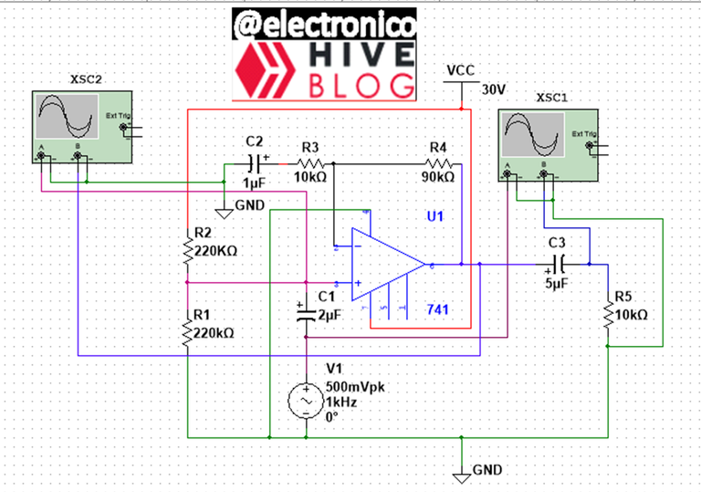
The positive source has two functions, the first is to feed the amplifier at its positive terminal and the second to bring the signal to the positive quadrant, for this R1 and R2 act as a voltage divider that will be added to the signal. C1 is a capacitor that couples both voltages (signal and DC).
R4 is at the position of Rf and R3 is at the position of Ri, these two resistors define the gain by the ratio A= (Rf+Ri)/Ri. For this case the gain is 10.
Since there will be a DC component in the output signal, capacitor C3 is used to decouple and obtain the amplified input signal (as it would happen if we use the 2 sources).
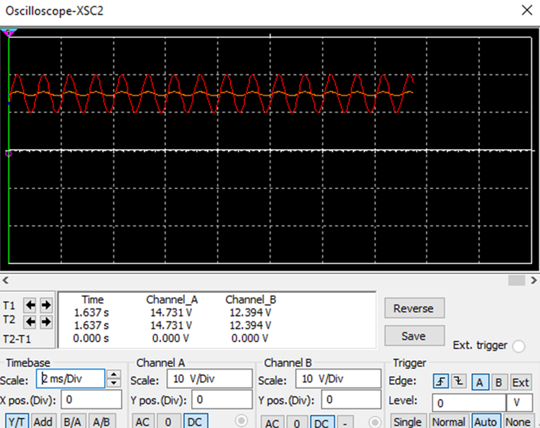
Using the XSC2 oscilloscope we can observe the signal coupled to the DC voltage, we can see that both the input and the amplified output will appear in the positive quadrant.
La fuente positiva tiene dos funciones, la primera es alimentar el amplificador en su terminal positivo y la segunda llevar la señal al cuadrante positivo, para ello R1 y R2 actúan como un divisor de voltaje que se sumará a la señal. C1 es un condensador que acopla ambos voltajes (el de la señal y el DC).
R4 está en la posición de Rf y R3 en la de Ri, estas dos resistencias definen la ganancia por la relacion A= (Rf+Ri)/Ri. Para este caso la ganancia es de 10.
Ya que existirá una componente DC en la señal de salida se usa el condensador C3 para desacoplar y obtener la señal de entrada amplificada (como ocurriría si usaramos las 2 fuentes).
Mediante el osciloscopio XSC2 podemos observar la señal acoplada al voltaje DC, podemos ver que tanto la entrada como la salida amplificada aparecerán en el cuadrante positivo.
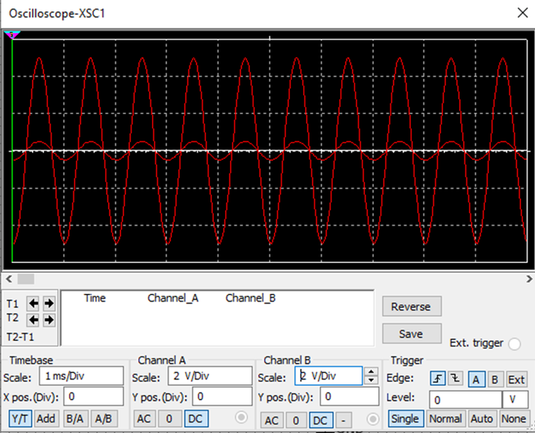
The XSC1 oscilloscope shows us the input signal and the amplified output signal, both decoupled from the DC voltage. It can be seen that both oscillate between the positive and negative quadrant and that the output is a faithful and exact copy of the input signal but amplified.
El osciloscopio XSC1 nos muestra la señal de entrada y la de salida amplificada, ambas desacopladas del voltaje DC. Se puede ver que ambas oscilan entre el cuadrante positivo y el negativo y que la salida es una copia fiel y exacta de la señal de entrada pero amplificada.
In this way you can build an amplifier with a single polarity. This is another of those circuits with operational amplifiers that are simple to design but very useful in some applications.
De esta forma se puede construir un amplificador con una sola polaridad. Este es otro de esos circuitos con amplificadores operacionales que son simples de diseñar pero muy útiles en algunas aplicaciones.
Nice one.
Ty
Yay! 🤗
Your content has been boosted with Ecency Points, by @electronico.
Use Ecency daily to boost your growth on platform!
Support Ecency
Vote for new Proposal
Delegate HP and earn more
Thanks for your contribution to the STEMsocial community. Feel free to join us on discord to get to know the rest of us!
Please consider delegating to the @stemsocial account (85% of the curation rewards are returned).
Thanks for including @stemsocial as a beneficiary, which gives you stronger support.
Congratulations @electronico! You have completed the following achievement on the Hive blockchain And have been rewarded with New badge(s)
Your next target is to reach 500 replies.
You can view your badges on your board and compare yourself to others in the Ranking
If you no longer want to receive notifications, reply to this comment with the word
STOPCheck out our last posts:
Great, I'm getting more interactions. Thanks for the tip.
You're welcome @electronico! Have a nice day 😊👍
¡Enhorabuena!
✅ Has hecho un buen trabajo, por lo cual tu publicación ha sido valorada y ha recibido el apoyo de parte de CHESS BROTHERS ♔ 💪
♟ Te invitamos a usar nuestra etiqueta #chessbrothers y a que aprendas más sobre nosotros.
♟♟ También puedes contactarnos en nuestro servidor de Discord y promocionar allí tus publicaciones.
♟♟♟ Considera unirte a nuestro trail de curación para que trabajemos en equipo y recibas recompensas automáticamente.
♞♟ Echa un vistazo a nuestra cuenta @chessbrotherspro para que te informes sobre el proceso de curación llevado a diario por nuestro equipo.
🏅 Si quieres obtener ganancias con tu delegacion de HP y apoyar a nuestro proyecto, te invitamos a unirte al plan Master Investor. Aquí puedes aprender cómo hacerlo.
Cordialmente
El equipo de CHESS BROTHERS