Selector for voltage source EN/ES
Sometimes it is required that a system is kept powered under different circumstances, this is commonly known as Uninterruptible Power Supply or UPS.
In this article we will learn how to design a simple source selector circuit, this is part of a project that I am designing but because it is a detailed project I could not take it all in one article due to the amount of content that can be generated.
So let's eat the cake by parts and for the purposes of this article we will study the source selector, its design and operation.
En ocasiones se requiere que un sistema se mantenga energizado bajo diferentes circunstancias, esto se conoce comúnmente como Sistema de Energía Ininterrumpida o UPS.
En este artículo aprenderemos a diseñar un circuito selector de fuente simple, este forma parte de un proyecto que estoy diseñando pero que por ser un proyecto detallado no podría ocuparlo todo en un solo artículo debido a la cantidad de contenido que se puede generar.
Entonces vamos a comernos el pastel por partes y para efectos de este artículo estudiaremos el selector de fuente, su diseño y funcionamiento.
Utility and operation |
|---|
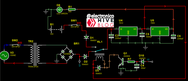
This circuit is useful when it is required to maintain an energized system having available two voltage sources to choose from, to better understand the operation we will describe it in parts.
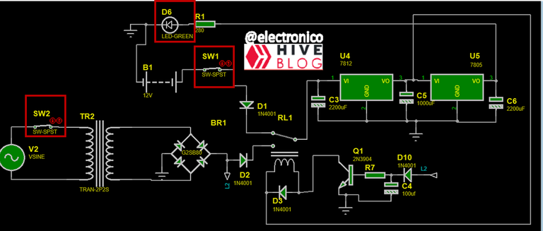
In the first part are representing two voltage sources, one DC corresponding to a 12V battery and one AC, the battery source can be replaced by an AC source similar to that raised without affecting the operation of the circuit, this makes it more flexible in terms of voltage sources that can be used.
Este circuito es útil cuando se requiere mantener un sistema energizado teniendo disponibles dos fuentes de voltaje para elegir, para comprender mejor el funcionamiento vamos a describirlo por partes.
En la primera parte se están representando dos fuentes de voltaje, una DC que corresponde a una Batería de 12V y uno AC, la fuente de la batería puede reemplazarse por una fuente AC similar a la planteada sin que esto afecte el funcionamiento del circuito, esto lo hace más flexible en cuanto a fuentes de voltaje que se pueden usar.
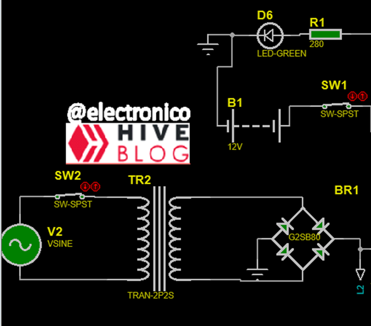
For the TR2 transformer we assume that the AC source has a voltage of 110Vrms and we use a transformation ratio 10:1, in any case if the source to use has a different value must ensure that in the secondary of the transformer there is a voltage greater than 10Vrms but not greater than 15Vrms in order to supply an adequate voltage to the logic circuit.
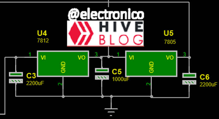
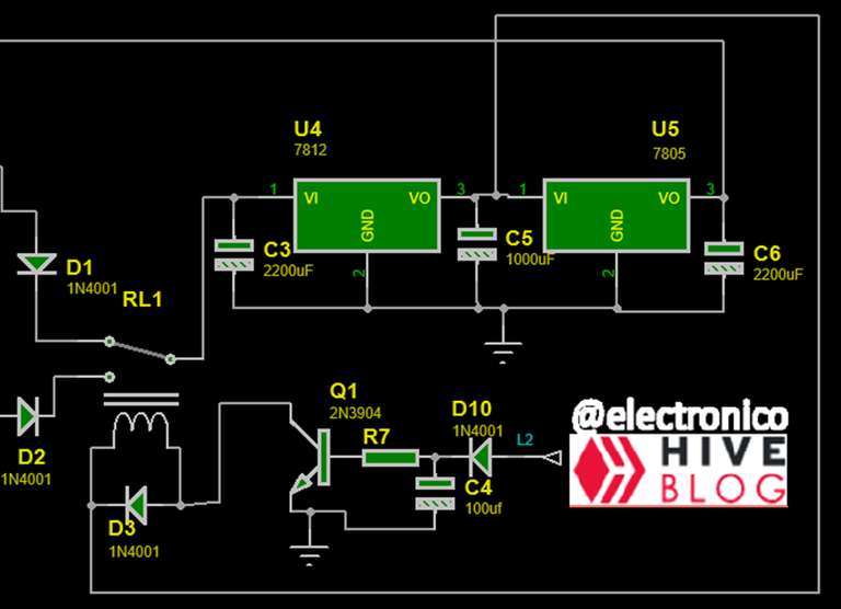
The output voltage is converted into a DC voltage whose value must be equal to or greater than 12VDC which are regulated with a LM7812 (12VDC) and are necessary to switch the relay responsible for selecting the source. Additionally a 5VDC regulator is added to be used in a control board if necessary, although for now we will only use them to turn on an indicator that will tell us when the system is energized.
Para el transformador TR2 asumimos que la fuente AC tiene un voltaje de 110Vrms y usamos una relación de transformación 10:1, en cualquier caso si la fuente a usar presenta un valor distinto se debe garantizar que en el secundario del transformador exista un voltaje superior a los 10Vrms pero no mayor a 15Vrms con la finalidad de suministrar un voltaje adecuado al circuito lógico.
El voltaje de salida se convierte en un voltaje DC cuyo valor debe ser igual o mayor que 12VDC los cuales se regulan con un LM7812(12VDC) y son necesarios para conmutar el relé encargado de elegir la fuente. Adicionalmente se añade un regulador de 5VDC para usar en alguna tarjeta de control si fuese necesario, aunque por ahora solo los usaremos para encender un indicador que nos dirá cuando el sistema está energizado.
The circuit in charge of doing the magic is a BJT transistor switching a relay, what is done is to adapt the second source so that when it is present energizes the base of the transistor and this in turn switches the relay to choose source 2, when source 2 is without energy the base of the transistor is de-energized and the relay switches again selecting source 1 as the main source.
A capacitor and a resistor are responsible for stabilizing the voltage at the base of the transistor keeping it energized long enough for the transition to occur.
El circuito encargado de hacer la magia es un transistor BJT conmutando un relé, lo que se hace es adaptar la segunda fuente para que al estár presente energize la base del transistor y ésta a su vez conmuta el relé para escoger la fuente 2, cuando la fuente 2 está sin energía la base del transistor se desenergiza y el relé vuelve a conmutar seleccionando la fuente 1 como la fuente principal.
Un capacitor y una resistencia se encargan de estabilizar el voltaje en la base del transistor manteniéndolo energizado el tiempo necesario para que ocurra la transición.
To test the operation, two switches have been added to simulate voltage losses in sources 1 and 2 and an LED will indicate whether the system is energized.
Para comprobar el funcionamiento se han añadido dos interruptores con los cuales vamos a simular pérdidas de voltajes en las fuentes 1 y 2 y un LED que nos indicará si el sistema está energizado.
Now let's simulate the circuit to check the correct operation, you can notice that source one must be present as initial condition for operation, after that if source 2 appears the circuit chooses this as the main source.
If source 2 is active and source 1 is lost the power supply is not affected, if source 2 is lost the circuit returns to source 1 and will return to source 2 only when it is available. In this way as long as one of the sources is available the system can operate without interruption.
Ahora vamos a simular el circuito para comprobar el correcto funcionamiento, se puede notar que la fuente uno debe estar presente como condición inicial para el funcionamiento, luego de eso si aparece la fuente 2 el circuito elige esta como fuente principal.
Si la fuente 2 está activa y la fuente uno se pierde la alimentación no se ve afectada, si la fuente 2 se pierde el circuito vuelve a la fuente 1 y regresará a la fuente 2 sólo cuando la misma esté disponible. De esta forma mientras una de las fuentes esté disponible el sistema podrá funcionar sin interrupciones.

I hope you find it useful, in the future we will make use of this circuit.
Espero que te sea de utilidad, en el futuro le daremos uso a este circuito.
If you want to give an extra boost to the blog with a donation you can send it to the addresses:
Si quieres darle un impulso extra al blog con una donación puedes enviarla a las direcciones:
BEP-20: 0x5Aee5e3e3ED3203e77eF0d8Bb3E3a420E5229Ce0
ERC-20: 0x5Aee5e3e3ED3203e77eF0d8Bb3E3a420E5229Ce0
Arbitrum One: 0x5Aee5e3e3ED3203e77eF0d8Bb3E3a420E5229Ce0
Polygon: 0x5Aee5e3e3ED3203e77eF0d8Bb3E3a420E5229Ce0
Avalanche: 0x5Aee5e3e3ED3203e77eF0d8Bb3E3a420E5229Ce0
Thanks for your contribution to the STEMsocial community. Feel free to join us on discord to get to know the rest of us!
Please consider delegating to the @stemsocial account (85% of the curation rewards are returned).
Thanks for including @stemsocial as a beneficiary, which gives you stronger support.