Reading and writing EEPROM memory on PIC16F877A ENG/ESP
In the previous article we introduced the topic of the EEPROM memories in microcontrollers investigating its functions in a microcontroller and the importance it can have in the development of some projects.
In this article we will go deeper into the subject making use of the EEPROM memory of the PIC16F877A, we will make a program that can store the data and we will see how to query the EEPROM memory data using the Proteus Software. We will also make a real application to check the permanence of the data in the memory after a power failure.
En el artículo anterior nos introdujimos al tema de las memorias EEPROM en microcontroladores indagando sobre sus funciones en un microcontrolador y la importancia que puede tener en el desarrollo de algunos proyectos.
En este artículo profundizaremos más el tema haciendo uso de la memoria EEPROM del PIC16F877A, haremos un programa que pueda almacenar los datos y veremos cómo consultar los datos de la memoria EEPROM usando el Software Proteus. También se hará una aplicación real para comprobar la permanencia de los datos en la memoria luego de un corte de energía.

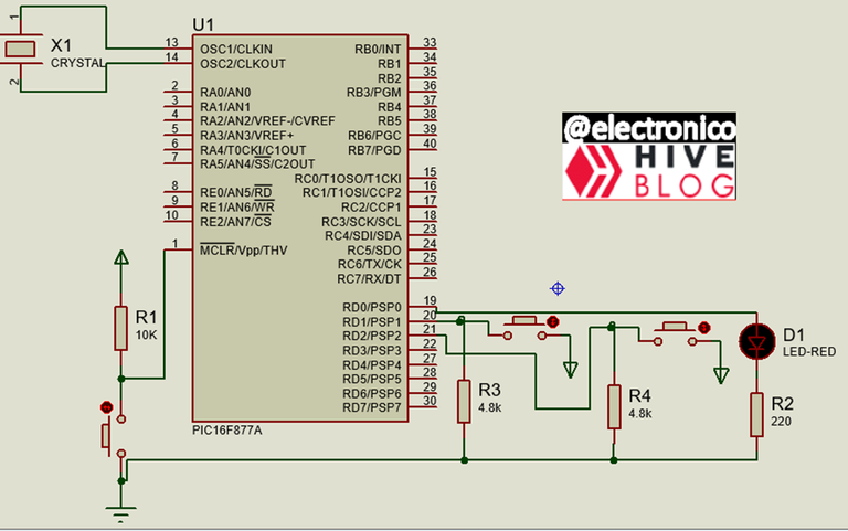
To demonstrate the use of EEPROM memory we are going to perform a simple application.
This application will consist of an LED, two pushbuttons and the PIC16F877A microcontroller (with the basic components it requires to operate such as crystal, capacitors and MCLR resistor).
Para demostrar el uso de la memoria EEPROM vamos a realizar una aplicación sencilla.
Esta aplicación consistirá en un LED, dos pulsadores y el microcontrolador PIC16F877A (con los componentes básicos que requiere para operar como cristal, capacitores y resistencia del MCLR).
The logic we will use is as follows:
With a pushbutton we are going to write a data in a register of the EEPROM memory, it can be any value between 0 and 255 because they are 8bits registers. In this case we have arbitrarily chosen to store the value 200.
In the program we are going to read the value stored in this register and when it is 200 we turn on the LED. The second pushbutton modifies this value to 100 so when the register is read the value is different from 200 and the LED will turn off.
In a program without EEPROM we could turn on the LED with the pushbutton but if when running the program from the beginning the LED turns off and does not turn on until the corresponding button is pressed then every time the power is cut and restored the LED will start off.
With the use of EEPROM in the case presented in this article we are going to demonstrate that if the LED was on when the power was cut it will remain on when the power is restored demonstrating that the data in the EEPROM memory remains stored even if the PIC loses power.
To accomplish this we are going to write some simple code. First the settings and create the eeprom variable that will be used to retrieve the data from any register in the eeprom.
La lógica que usaremos es la siguiente:
Con un pulsador vamos a escribir un dato en un registro de la memoria EEPROM, puede ser cualquier valor entre 0 y 255 porque son registros de 8bits. En este caso arbitrariamente se ha escogido almacenar el valor 200.
En el programa vamos a leer el valor almacenado en este registro y cuando sea 200 encendemos el LED. El segundo pulsador modifica este valor a 100 por lo tanto cuando se lee el registro el valor es distinto de 200 y se apagará el LED.
En un programa sin EEPROM podríamos encender el LED con el pulsador pero si al correr el programa desde el inicio el LED se apaga y no enciende hasta que se pulse el botón correspondiente entonces cada vez que se corte y restablezca la energía el LED iniciará apagado.
Con el uso de EEPROM en el caso que se plantea en este artículo se va a demostrar que si el LED estaba encendido al cortar la energía seguirá encendido al restablecer la energía demostrando que el dato en la memoria EEPROM se mantiene almacenado aunque el PIC pierda la energía.
Para lograr esto vamos a escribir un código sencillo. Primero las configuraciones y se crea la variable eeprom que se usará para recuperar los datos de cualquier registro en la eeprom.
#include <16f877a.h>
#fuses HS,NOWDT,NOPROTECT,NOPUT,NOLVP,BROWNOUT
#use delay(clock=16.8M)
#use standard_io(D)

#Define push_on PIN_D1
#Define push_off PIN_D2
#Define LED        PIN_D0
int eeprom;
Before the infinite loop in the main program, a line is written to force the LED to turn off when the program starts, thus avoiding erroneous switching on due to floating states.
Antes del bucle infinito en el programa principal se escribe una línea que obliga a apagar el LED cuando el programa inicia, de esta forma evitamos encendidos erróneos por estados flotantes.
void main()
{
   output_low(LED);
Then in the infinite while loop we evaluate the state of the first push button (push_on) and when it is pressed the value 200 is written in register 1 of the EEPROM memory, a delay of 100ms is established so that the writing is done correctly.
Luego en el bucle while infinito evaluamos el estado del primer pulsador (push_on) y al ser pulsado se escribe el valor 200 en el registro 1 de la memoria EEPROM, se establece un retardo de 100ms para que se haga la escritura correctamente.
 while(true)
   {
      if(input(push_on) == 1)
      {
       write_eeprom(1, 200);
       delay_ms(100);
      }
We do the same for the second push button (push_off) but instead of 200 we write 100 to make the value different from 200 and turn off the LED.
Se hace lo mismo para el segundo pulsador (push_off) pero en lugar de 200 escribimos 100 para hacer que el valor sea distinto a 200 y se apague el LED.
      if(input(push_off) == 1)
      {
       write_eeprom(1, 100);
       delay_ms(100);
      }
Now we load the value contained in register 1 of the EEPROM memory into the eeprom variable to be used in the following lines.
Ahora cargamos el valor que contenga el registro 1 de la memoria EEPROM en la variable eeprom para darle uso en las siguientes líneas.
eeprom = read_eeprom(1);
Finally we set the dependency for the LED on, as in this case it will depend on the value stored in the EEPROM then the state of the LED will be maintained even if a program reset occurs.
Finalmente establecemos la dependencia para el encendido del LED, como en este caso dependerá del valor guardado en la EEPROM entonces el estado del LED se mantendrá incluso si ocurre un reinicio del programa.
      if(eeprom == 200)
      {
       output_high(LED);
      }
      else
      {
       output_low(LED);
      }
   }
}
Proteus despite being a simulation software also takes into account the EEPROM memory data, for that reason, although I have made a real circuit for this demonstration I will also make a simulation in Proteus as I consider important to know these details of the simulator.
Proteus a pesar de ser un software de simulación también toma en cuenta los datos de la memoria EEPROM, por esa razón, aunque he hecho un circuito real para esta demostración también haré una simulación en Proteus ya que considero importante conocer estos detalles del simulador.
When running the simulation the LED is observed off which is logical because we established a line that turns it off during startup, as no button has been pressed yet register 1 of the EEPROM memory is 0 and as 0 is different from 200 the LED remains off.
Then each of the buttons is pressed to check its operation and it can be seen that one turns on the LED and the other turns it off correctly.
Finally the LED is turned on and the simulation is stopped, then the simulation is started again and it can be verified that the LED on state is maintained, the same is done for the off state and it is verified that the program complies with what has been described.
To finish with this article I have prepared a real circuit in which we are going to provoke each of the states and check that by cutting and restoring power the states are maintained.
Al correr la simulación el LED se observa apagado lo cual es lógico porque establecimos una línea que lo apaga durante el inicio, como aún no se ha pulsado ningún botón el registro 1 de la memoria EEPROM vale 0 y como 0 es distinto de 200 el LED permanece apagado.
Luego se pulsa cada uno de los botones para comprobar su funcionamiento y se puede ver que uno enciende el LED y el otro lo apaga de forma correcta.
Finalmente se enciende el LED y se detiene la simulación, luego se inicia nuevamente la simulación y se puede comprobar que el estado encendido del LED se mantiene, se hace lo mismo para el estado apagado y se comprueba que el programa cumple con lo descrito.
Para terminar con este artículo he preparado un circuito real en el que vamos a provocar el cada uno de los estados y comprobar que al cortar y restablecer la energía los estados se mantienen.
With this demonstration it is clear how the EEPROM works, the data stored was 200 but a variable such as temperature, level, pressure, flow or any other data of interest could have been stored.
As each register is limited to 8bits if you want to store a larger data (greater than 255 for example) you can use two registers and make a 16bits data.
I thank you very much for the time spent reading. I hope this information has been useful for you.
Con esta demostración queda claro el funcionamiento de la EEPROM, el dato almacenado fue 200 pero se pudo haber almacenado una variable como temperatura, nivel, presión, flujo o cualquier otro dato de interés.
Como cada registro está limitado a 8bits si se desea almacenar un dato mayor (mayor que 255 por ejemplo) se pueden usar dos registros y conformar un dato de 16bits.
Te agradezco mucho por el tiempo dedicado a la lectura. Me despido esperando que esta información te haya sido de utilidad.
If you want to give an extra boost to the blog with a donation you can send it to the addresses:
Si quieres darle un impulso extra al blog con una donación puedes enviarla a las direcciones:
BEP-20: 0x5Aee5e3e3ED3203e77eF0d8Bb3E3a420E5229Ce0
ERC-20: 0x5Aee5e3e3ED3203e77eF0d8Bb3E3a420E5229Ce0
Arbitrum One: 0x5Aee5e3e3ED3203e77eF0d8Bb3E3a420E5229Ce0
Polygon: 0x5Aee5e3e3ED3203e77eF0d8Bb3E3a420E5229Ce0
Avalanche: 0x5Aee5e3e3ED3203e77eF0d8Bb3E3a420E5229Ce0
Great read. What other things can be done with the eeprom?
!PIMP
You must be killin' it out here!
@wanderingmoon just slapped you with 1.000 PIMP, @electronico.
You earned 1.000 PIMP for the strong hand.
They're getting a workout and slapped 1/1 possible people today.
Read about some PIMP Shit or Look for the PIMP District
The essence is to be able to store data that is maintained even if the microcontroller is restarted. This data can be process variables, time, among many other things that may arise from the creativity of the program developer and the needs of the process where it will be applied.
Thanks for the visit!
I would like to see you do a post using a breadboard to do a firmware read.
I was wondering if I were to build a PCB for such a project how could I compensate for the different ic/mcu sizes? Is there also a difference in the size vs pin count?
So far the designs I make for real testing I try to base them on the components I have on hand and use a breadboard so I can easily reuse them. Making an electronic board would imply an additional expense and it doesn't make sense if I won't give it a real use (unless the money comes from donations), recently I have created some but they were for private projects and I can't publish them because when I get paid for those projects they don't belong to me (I don't own the copyright), but if I find the need to make one for myself I will share it happily.
Regarding the size vs number of pins in microcontrollers I think it is not the correct relationship to consider, there are microcontrollers for SMD assembly that have up to 80 pins and are smaller than the 40 as the one shown in this article, on the other hand neither the size and number of pins defines the power or capabilities of the microcontroller, for example the 18f2550 has 28 pins and is smaller than the 16f877a but has up to 4 times more power. I think that the number of pins is only important if you will use many inputs and outputs, but not as a priority because there are components that allow to expand the connection capabilities in microcontrollers of few pins.
Thanks for your contribution to the STEMsocial community. Feel free to join us on discord to get to know the rest of us!
Please consider delegating to the @stemsocial account (85% of the curation rewards are returned).
Thanks for including @stemsocial as a beneficiary, which gives you stronger support.
Thank you!!!