PIC18F2550 USB-CDC communication EN/ES
Now that we have implemented the physical connections to communicate our PIC18F2550 with the computer via USB is the right time to start taking advantage of this feature, so let's check the enormous advantage that brings this direct communication and the two possible ways to do it.
In this article we are going to mention and approach in a superficial way the USB-HID communication and then focus on USB-CBC finding the proper use for each mode and establishing the differences and conveniences for each occasion.
But we are not only going to describe commands or configurations, I want this article to be special and that is why I have chosen directly from my recycling warehouse a motor with PWM control capability that at the same time has encoder to monitor the RPM, then we will additionally make a control program with LABVIEW that will communicate via USB-CBC with our breadboard for that purpose.
This promises to be a very complete article!
Ahora que tenemos implementadas las conexiones físicas para comunicar nuestro PIC18F2550 con el ordenador mediante USB es el momento oportuno para comenzar a aprovechar esta característica, así vamos a comprobar la enorme ventaja que aporta esta comunicación directa y los dos modos posibles de hacerlo.
En este artículo vamos a mencionar y abordar de forma superficial la comunicación USB-HID para luego centrarnos en USB-CBC encontrando el uso adecuado para cada modo y estableciendo las diferencias y conveniencias para cada ocasión.
Pero no solo vamos a describir comandos o configuraciones, quiero que este artículo sea especial y por eso he escogido directamente de mi almacén de reciclaje un motor con capacidad de ser controlado por PWM que a la vez tiene encoder para monitorear las RPM, entonces haremos adicionalmente un programa de control con LABVIEW que se comunicará mediante USB-CBC con nuestro protoboard para dicho propósito.
¡Esto promete ser un artículo muy completo!
The hardware |
|---|
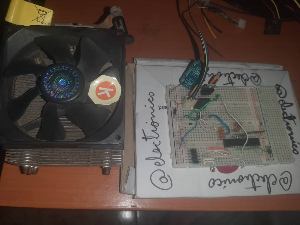
If you noticed that thing is nothing more than a processor cooler, a fan mounted on a heat sink which in turn is mounted on a processor on a computer motherboard.
But this is not just any fan, at first we can interpret it as a DC motor with brushes because we only feed with a DC voltage and we make it go but in reality this is not true and just see that the rotor is externally suggesting a cover that internally has magnets and a brushless type operating principle.
What makes its control easy is that internally has the electronic arrangement that is responsible for doing the work, in fact we may notice that apart from the power supply (yellow and black wires) has two additional wires, one is to control the speed by PWM (blue wire) and the other to read pulses by which you can get the RPMs (green wire).
Si lo notaste aquella cosa no es más que un enfriador de procesadores, un ventilador montado sobre un disipador de calor que a su vez va montado sobre un procesador en una tarjeta madre de ordenador.
Pero este no es un ventilador cualquiera, a principio podemos interpretarlo como un motor DC con escobillas ya que solo alimentamos con un voltaje DC y lo hacemos andar pero en la realidad esto no es cierto y basta con solo ver que el rotor está de forma externa lo que sugiere una cubierta que internamente tiene imanes y un principio de funcionamiento tipo brushless.
Lo que hace que su control sea fácil es que internamente posee el arreglo electrónico que se encarga de hacer la labor, de hecho podremos notar que a parte de la alimentación (cables amarillo y negro) posee dos cables adicionales, uno es para controlar la velocidad mediante PWM (Cable azul) y el otro para leer pulsos mediante los cuales se pueden obtener las RPMs (cable verde).
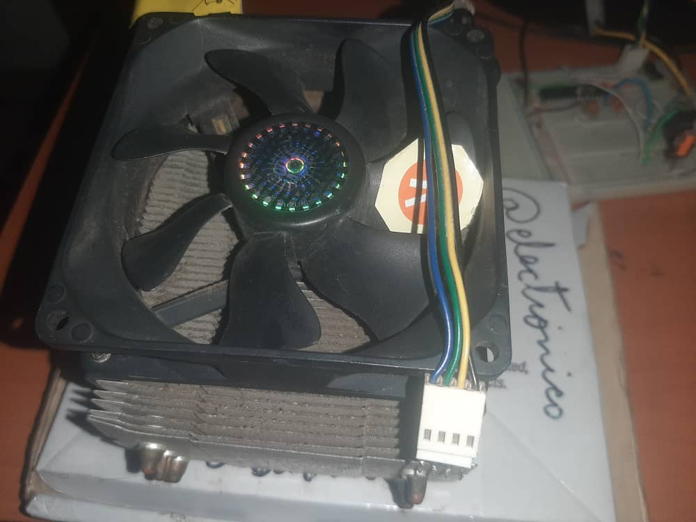
It would be enough to connect the yellow wire to +VDD, the black wire to Vss and we can control the speed by sending a PWM signal through the blue wire which in turn we can monitor by connecting the green wire to an input of the microcontroller configured for such reading.
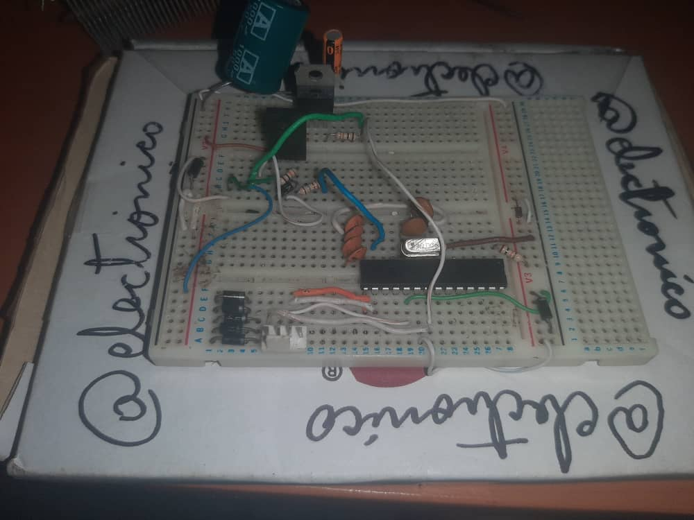
In practice we must protect exaggeratedly our microcontroller (it is just bought and I don't want to damage it... yet), since we are going to feed our breadboard with 12VDC we will use a LM7805 voltage regulator to provide 5VDC voltages to all the stages that will interact with the microcontroller, and we will couple the PWM with an IRF630 MOSFET.
Maybe it can be connected directly between the microcontroller and the motor but as I don't have the motor datasheet I prefer not to risk.
As for the pulse readout, the edges are low... this means that we must place a high value on the read input and the pulse will switch it to a low state.
Bastaría con conectar el cable amarillo a +VDD, el negro a Vss y podremos controlar la velocidad enviando una señal PWM por el azul que a su vez podemos monitorear conectando el cable verde a una entrada del microcontrolador configurada para dicha lectura.
En la práctica debemos proteger exageradamente nuestro microcontrolador (está recién comprado y no lo quiero dañar... aún), ya que vamos a alimentar nuestra protoboard con 12VDC usaremos un regulador de voltaje LM7805 para aportar voltajes de 5VDC a todas las etapas que van a interactuar con el microcontrolador, y acoplaremos el PWM con un MOSFET IRF630.
Tal vez se pueda conectar directamente entre el microcontrolador y el motor pero como no tengo la hoja de datos del motor prefiero no arriesgar.
En cuanto a la lectura de pulsos, los flancos son de bajada... esto quiere decir que debemos colocar un valor alto sobre la entrada lectora y el pulso lo conmutará a un estado bajo.

The above circuit is a close representation of the actual circuit since the motor used is of a different type, I am not including the LM7805 regulator and in the case of the 400nF capacitor I am using 4 of 100nF in parallel (they add up to 400nF).
El circuito anterior es una representación cercana del circuito real ya que el motor usado es de otro tipo, no estoy incluyendo el regulador LM7805 y en el caso del capacitor de 400nF estoy usando 4 de 100nF en paralelo (suman los 400nF).
The software |
|---|
The program will have... for the time being... only two functions: Read the pulses to make the conversion to RPMs sending this value to the computer (LabView) and receive a value of 8Bits from the computer (LabView) for the PWM control.
The communication will obviously be done via USB, here we will take the opportunity to describe the two possible modes.
USB-HID: It is a type of communication used in Human Interface Devices, these are commonly used devices such as keyboards, mice and others with specific functions, in this case the computer recognizes the device as soon as it is connected to the USB port. The disadvantage is that only 8Bits data frames can be sent, if we need to transmit for example a 10Bits ADC value we have to send two 8Bits frames to be able to represent it (I will consider writing an article about this in the future).
USB-CDC: This is interpreted as a kind of device for communications, an easy way to understand it is that we can use the USB port for serial communication as we did with UART communication, it is even the same configuration for LabView, hence I choose this mode as preferred since during the construction of the blog we have learned to familiarize ourselves with it.
El programa tendrá... por ahora... únicamente dos funciones: Leer los pulsos para hacer la conversión a RPMs enviando dicho valor al ordenador (LabView) y recibir un valor de 8Bits desde el ordenador (LabView) para el control del PWM.
La comunicación se hará obviamente mediante USB, aquí aprovecharemos para describir los dos modos posibles.
- USB-HID: Es un tipo de comunicación que se usa en Dispositivos de Interfaz Humana, estos son dispositivos de uso común como teclados, ratones y otros con funciones específicas, en este caso el ordenador reconoce el dispositivo apenas es conectado al puerto USB. La desventaja es que solo se pueden enviar tramas de datos de 8Bits, si necesitamos transmitir por ejemplo un valor ADC de 10Bits tenemos que enviar dos tramas de 8Bits para poderlo representar (Voy a considerar escribir un artículo sobre esto en el futuro).
- USB-CDC: Esto se interpreta como una clase de dispositivo para comunicaciones, una forma fácil de entenderlo es que podemos usar el puerto USB para una comunicación serial tal como lo hacíamos con la comunicación UART, incluso es la misma configuración para LabView, de ahí que escoja este modo como preferido ya que durante la construcción del blog hemos aprendido a familiarizarnos con él.
In LabView |
|---|
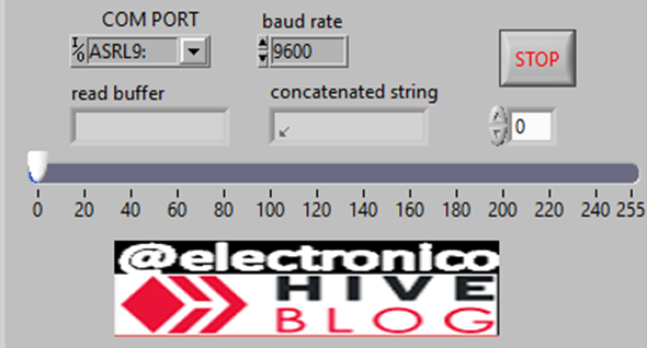
The configuration to communicate with the serial port is the same as always, we use a flag to capture the incoming data and a slide to generate the data to send passing this numerical data through a string converter.
Necesitamos recibir y mostrar una cadena de caracteres proveniente del microcontrolador que contiene el valor de las RPMs, y necesitamos enviar un dato cuyo valor esté entre 0 y 255 para el control del PWM.
La configuración para comunicarnos con el puerto serial es la misma de siempre, usamos un indicador para capturar los datos entrantes y un slide para generar los datos a enviar pasando dicho dato numérico por un convertidor a cadena de caracteres.
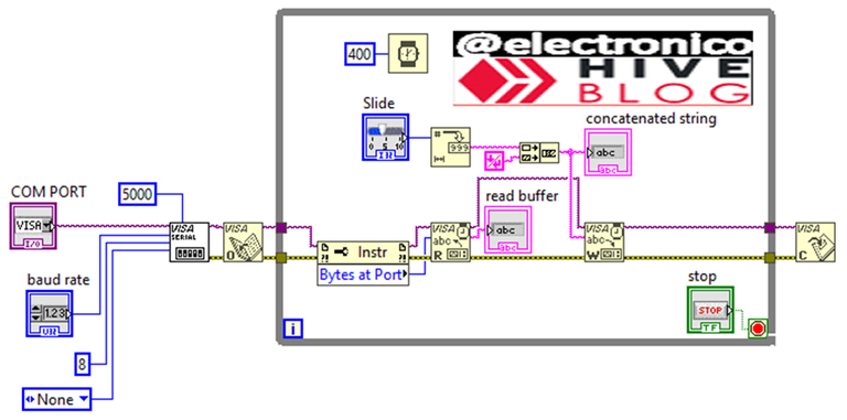
Our front panel would look as shown in the following image:
Nuestro panel frontal quedaría tal como se muestra en la siguiente imágen:
Programming the microcontroller |
|---|
The 18F series has more fuses than the ones we are used to configure with the PIC16F877A, in the following code we will see this difference, the crystal frequency is 20MHz, and to work with USB-CBC and handle character strings with this communication mode we will use the libraries usb_cdc. h and usb_cdc_string.h, as a nostalgic act I have also included the integer_serial.c library in case we need to use its functions and map_function.c for a certain arrangement that I will describe a few lines later.
If to all the above we add the configuration of the ports to use our configuration lines are as follows:
La serie 18F tiene más fuses que los que acostumbramos a configurar con el PIC16F877A, en el siguiente código veremos esta diferencia, la frecuencia del cristal es de 20MHz, y para trabajar con USB-CBC y manejar cadenas de caracteres con esto modo de comunicación usaremos las librerías usb_cdc.h y usb_cdc_string.h, como un acto nostálgico he incluído también la librería integer_serial.c por sí nace la necesidad de usar sus funciones y map_function.c para cierto arreglo que describiré unas líneas más adelante.
Si a todo lo anterior añadimos las configuración de los puertos a usar nuestras líneas de configuración quedan de la siguiente forma:
#include <18f2550.h>
#device PASS_STRINGS = IN_RAM
#fuses HS,NOWDT,NOPROTECT,NOLVP,PUT,CPUDIV1,NODEBUG,USBDIV,PLL5,VREGEN,NOPBADEN
#use delay(Clock=20000000)
#use standard_io(C)
#use fast_io(B)
#include <usb_cdc.h
#include <usb_cdc_string.h
#include <integer_serial.c
#include <map_function.c
I consider necessary 6 variables, one Char type (String) to handle the data received from the computer with this format, 3 int type (pwm_value to convert String to int, pwm_go to adapt this signal to the one required by the PWM and pul_rev that is required in the pulse reading, this variable defines the number of blades of our motor and thus every how many pulses is considered a turn), one double type (RPM to represent the value of the RPMs read) and one long type (Counter) to count the pulses received.
Considero necesarias 6 variables, una tipo Char (String) para manejar los datos recibidos desde el ordenador con dicho formato, 3 tipo int (pwm_value para convertir String a int, pwm_go para adaptar esta señal a la requerida por el PWM y pul_rev que se requiere en la lectura de pulsos, esta variable define la cantidad de aspas de nuestro motor y con ello cada cuantos pulsos se considera una vuelta), una de tipo double (RPM para representar el valor de las RPMs leídas) y una de tipo long (Counter) para contar los pulsos recibidos.
char string[10];
int pwm_value;
int pwm_go;
long counter = 0;
double RPM;
int pul_rev = 7;
We will use the external interrupt RB0 to read the pulses that will allow us to calculate the RPM, these pulses are accumulated in the counter variable.
Usaremos la interrupción externa RB0 para leer los pulsos que nos permitirán calcular las RPM,s estos pulsos los acumulamos en la variable counter.
#INT_EXT
void RB0_RPM_COUNTER()
{
  counter++;
}
In the main program we initialize the USB-CBC and USB communication in general, configure the ccp1 module as pwm, port B as input and enable the RB0 interrupt for falling edges (remember that this is the way the signal comes from the green cable).
En el programa principal inicializamos la comunicación USB-CBC y USB en general, configuramos el módulo ccp1 como pwm, el puerto B como entrada y habilitamos la interrupción RB0 por flancos de bajada (recordemo que es la forma en que viene la señal del cable verde).
void main()
{
   usb_cdc_init();
   usb_init();
   setup_timer_2(t2_div_by_16, 255, 1);
   setup_ccp1(ccp_pwm);
   set_pwm1_duty(255);
   set_tris_b(0xFF);
   enable_interrupts(INT_EXT);
   ext_int_edge(H_TO_L);
   enable_interrupts(GLOBAL);
At this point I will explain how we will use the PWM, if you could notice it was initially loaded with the maximum value 255, thanks to the arrangement I made in protection mode with the Mosfet IRF630 the PWM signal acts in reverse, a high edge will reach the mosfet gate and will switch the signal that reaches the motor as a 0, so that when a high edge is sent the motor receives a low edge and vice versa.
In other words the maximum RPM's will be obtained when the pwm has a value of 0 and minimum for a value of 255, this can be confusing for an operator, that's why I have used the map_function.c library and the pwm_go variable so that this process can be done without affecting the way we are used to see the pwm.
To start the USB communication a protocol must be fulfilled, first usb_task(); sends the communication request while usb_enumerated() will throw a true value when the computer has accepted the communication and is ready to execute it, usb_cdc_kbhit() is true when a data has been received and usb_read_string allows us to store that data in a variable, printf(usb_cdc_putc, "data") allows us to transmit a data.
Knowing all the above, the order of functions is written below:
En este punto paso a explicar cómo usaremos el PWM, si pudiste notar fue cargado inicialmente con el valor máximo 255, gracias al arreglo que hice en modo de protección con el Mosfet IRF630 la señal PWM actúa de forma invertida, un flanco alto llegará a la puerta del mosfet y conmutará la señal que llega al motor como un 0, de manera que cuando se envía un flanco alto el motor recibe un flanco bajo y viceversa.
Dicho de otra forma se obtendrán las RPM's máximas cuando el pwm tenga un valor de 0 y mínimas para un valor de 255, esto puede ser confuso para un operador, es por eso que he usado la librería map_function.c y la variable pwm_go para que este proceso se pueda realizar sin que afecte la forma como estamos acostumbrados a ver el pwm.
Para comenzar la comunicación USB se debe cumplir un protocolo, primero usb_task(); envía la solicitud de comunicación mientras que usb_enumerated() arrojará un valor verdadero cuando el ordenador haya aceptado la comunicación y esté listo para ejecutarla, usb_cdc_kbhit() es verdadero cuando se ha recibido un dato y usb_read_string nos permite almacenar ese dato en una variable, printf(usb_cdc_putc,"dato") nos permite transmitir un dato.
Sabiendo todo lo anterior el orden de funciones se escribe a continuación:
while(true)
   {

      usb_task();
      if(usb_enumerated())
      {
         if(usb_cdc_kbhit())
         {
          usb_read_string(string, 10);
          pwm_value = string_to_int(string, data_8_bit);
          pwm_go=map(pwm_value, 0, 255, 255, 0);
          set_pwm1_duty(pwm_go);
          RPM = counter*150/pul_rev;
          printf(usb_cdc_putc,"RPM: %f \r\n",RPM);
         }
      }

     delay_ms(400);
     counter = 0;
   }
We can notice the line pwm_go=map(pwm_value, 0, 255, 255, 0); by means of which a conversion is made for the PWM, when a 0 is received it converts it into 255 for the variable pwm_go and when a 255 converts it into a 0, the same for intermediate values making an adaptation between the received signal and the equivalent signal to load in the pwm.
It also highlights the line RPM = counter*150/pul_rev; that we use to calculate the RPMs, remember that counter stores the pulses, if we notice the delay_ms(400) we will know that this equation is executed every 400 milliseconds, then the value of counter is the amount of pulses that have been stored every 400ms, those pulses we divide them by pul_rev that is the number of blades to obtain the number of turns.
That is, counter/pul_rev will tell us the number of turns counted during 400ms, but in one minute there are 150 times 400ms or 60s/0.4s=150, this means that for each turn that is counted during 400ms must be counted 150 for 1minute, or 1 turn every 400ms is equivalent to 150RPM's.
Podemos notar la línea pwm_go=map(pwm_value, 0, 255, 255, 0); mediante la cual se hace una conversión para el PWM, cuando se recibe un 0 lo convierte en 255 para la variable pwm_go y cuando un 255 lo convierte en un 0, lo mismo para valores intermedios haciendo una adaptación entre la señal recibida y la señal equivalente a cargar en el pwm.
También resalta la línea RPM = counter*150/pul_rev; que utilizamos para calcular las RPMs, recordemos que counter almacena los pulsos, si notamos el delay_ms(400) sabremos que esta ecuación se ejecuta cada 400 milisegundos, entonces el valor de counter es la cantidad de pulsos que se han almacenado cada 400ms, esos pulsos los dividimos entre pul_rev que es el número de aspas para así obtener el número de vueltas.
Es decir, counter/pul_rev nos dirá el número de vueltas contadas durante 400ms, pero en un minuto hay 150 veces 400ms o 60s/0.4s=150, esto quiere decir que por cada vuelta que se cuente durante 400ms se deben contar 150 para 1minuto, o 1 vuelta cada 400ms equivale a 150RPM's.
Verifying |
|---|
To check that everything has gone well we connect the PIC to the computer and run the program in LabView, we can see that it is reading correctly the RPM's, we will also see how to vary the Slide varies the motor speed and is also reflected in the variation of the RPM's.
Para comprobar que todo ha salido bien conectamos el PIC al ordenador y ejecutamos el programa en LabView, podemos notar que está leyendo correctamente las RPM's, además veremos como al variar el Slide se varía la velocidad del motor y también se refleja en la variación de las RPM's.
Creating the animations from videos captured by the phone is becoming complicated for me because of the weight of them, I have to sacrifice quality so that they acquire the necessary size to upload them to the blog, if you can not see the details well I have opened a youtube channel to additionally upload the video. In the following link you will see the process maybe a little clearer.
Crear las animaciones partiendo de videos capturados por el teléfono se me está haciendo complicado por el peso de los mismos, tengo que sacrificar calidad para que adquieran el tamaño necesario para subirlos al blog, si no se pueden apreciar bien los detalles he abierto un canal en youtube para adicionalmente subir el video. En el siguiente enlace verás el proceso quizás un poco más claro.
https://youtube.com/shorts/Qkrc8NTa3CM
If you want to give an extra boost to the blog with a donation you can send it to the addresses:
Si quieres darle un impulso extra al blog con una donación puedes enviarla a las direcciones:
BEP-20: 0x5Aee5e3e3ED3203e77eF0d8Bb3E3a420E5229Ce0
ERC-20: 0x5Aee5e3e3ED3203e77eF0d8Bb3E3a420E5229Ce0
Arbitrum One: 0x5Aee5e3e3ED3203e77eF0d8Bb3E3a420E5229Ce0
Polygon: 0x5Aee5e3e3ED3203e77eF0d8Bb3E3a420E5229Ce0
Avalanche: 0x5Aee5e3e3ED3203e77eF0d8Bb3E3a420E5229Ce0
Thanks for your contribution to the STEMsocial community. Feel free to join us on discord to get to know the rest of us!
Please consider delegating to the @stemsocial account (85% of the curation rewards are returned).
Thanks for including @stemsocial as a beneficiary, which gives you stronger support.