Luminous voltmeter EN/ES
In the world of electronics there are applications that can be both simple to build and useful, in that sense I have always had a great respect for operational amplifiers, I think that after the transistor these are undoubtedly one of the most useful components in analog electronics.
In spite of that I think they have not been done much justice in the blog, that's why I will try to balance the balance a little bit by adding some useful designs based on operational amplifiers.
This time we will see how a configuration of amplifiers combined with resistors and diodes can be used as voltage meters.
En el mundo de la electrónica existen aplicaciones que pueden ser tanto sencillas de construir como útiles, en ese sentido siempre he tenido un gran respeto por los amplificadores operacionales, creo que después del transistor estos son sin duda alguna uno de los componentes con mayor utilidad en la electronica analogica.
A pesar de ello creo que no se les ha hecho mucha justicia en el blog, es por eso que intentaré equilibrar un poco la balanza añadiendo algunos diseños útiles basados en amplificadores operacionales.
En esta ocasión veremos como una configuración de amplificadores combinados con resistencias y diodos pueden hacer la función de medidores de voltaje.
A voltmeter is a tool used to measure voltage, nowadays it is difficult to find one that does not have digital technology and a display to show the values in the measurement.
With operational amplifiers we can build one without display, for the indicative part we can use LED's where each LED will represent a voltage value.
If we use an amplifier as a comparator and compare an unknown input connected to the non-inverting input with a known voltage connected to the inverting input we will know that if the output is positive then the unknown voltage will give us a clue to its value by knowing that it is higher or lower than the known one depending on the output of the comparator.
If we use two comparators it is now possible to narrow down a measurement range to know if the unknown value is within that known range. With all this in mind let's look at the following image.
Un voltímetro es una herramienta que sirve para medir voltaje, en la actualidad es difícil encontrar uno que no tenga tecnología digital y una pantalla para mostrar los valores en la medición.
Con amplificadores operacionales podemos construir uno sin display, para la parte indicativa se pueden usar LED's donde cada LED representará un valor de voltaje.
Si usamos un amplificador como comparador y comparamos una entrada desconocida conectada en la entrada no inversora con un voltaje conocido conectado en la entrada inversora sabremos que si la salida es positiva entonces el voltaje desconocido nos arrojará una pista de su valor al saber que es mayor o menor que el conocido segun sea la salida del comparador.
Si usamos dos comparadores ahora es posible acotar un rango de medición para saber si el valor desconocido se encuentra dentro de ese rango conocido. Con todo esto en mente vamos a mirar la siguiente imagen.
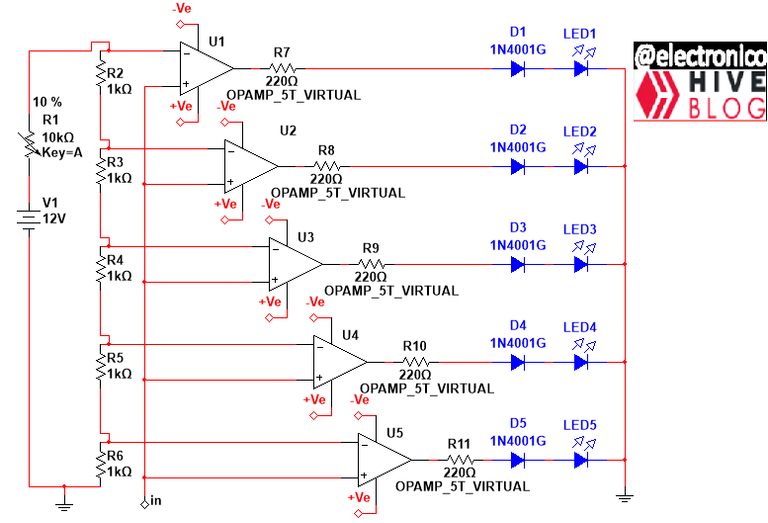
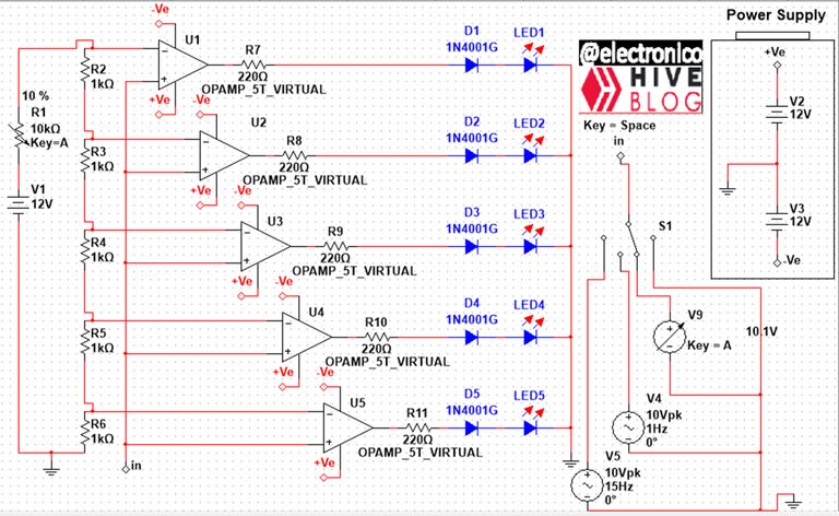
Each amplifier allows to represent a voltage value, in this case 5 values are represented, if more are desired more amplifiers must be added.
The 1K resistors allow to define the voltage value that will add each LED on, the source V1 and the potentiometer are coupled to all the resistors to produce a fixed current through each 1K resistor.
The value of this current is used to determine how much voltage represents the lighting of an LED, for this Ohm's Law is used, if we circulate 1mA through the branch each LED will have a representation of 1V, being all the resistors equal the margin of error is 1V since there will only be changes when the value changes to zero or 2V.
You can increase or decrease this resolution by varying the potentiometer, for this case I am using 2V range so I can measure between 0 and 10V. The voltage to be measured is connected in common to the non-inverting input of all the amplifiers involved.
The other part of the circuit is shown below:
Cada amplificador permite representar un valor de voltaje, en este caso se representan 5 valores, si se desean más se deben añadir más amplificadores.
Las resistencias de 1K permiten definir el valor de voltaje que sumará cada LED encendido, la fuente V1 y el potenciómetro se acoplan a todas las resistencias para producir una corriente fija a través de cada resistencia de 1K.
El valor de dicha corriente sirve para determinar cuánto voltaje representa el encendido de un LED, para ello se usa la Ley de Ohm, si hacemos circular 1mA por la rama cada LED tendrá una representación de 1V, al ser todas las resistencias iguales el margen de error es 1V ya que solo habrán cambios cuando el valor cambie a cero o 2V.
Se puede aumentar o disminuir esta resolución variando el potenciómetro, para este caso estoy usando 2V de intervalo de manera que puedo medir entre 0 y 10V. El voltaje que se desea medir es conectado de forma común a la entrada no inversora de todos los amplificadores involucrados.
La otra parte del circuito se muestra a continuación:
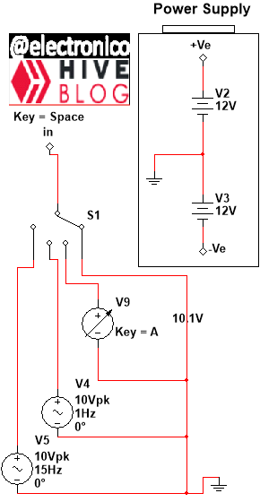
We have the configuration of two sources to feed the operational amplifiers and we can also see a selector of 4 inputs x 1 output, to each input of the selector a voltage source with different characteristics will be connected, the selector will allow to connect one of them to the input to make measurements.
One source generates a sinusoidal voltage with a frequency of 15Hz, we will see the effect of the variation reflected in the lighting of the LEDs, the other source is similar in voltage and waveform but with a frequency of 1Hz, that implies a slower variation.
A variable DC source will allow us to enter values manually to evaluate the response of the circuit and the last connection on the selector is to ground for cases where there is no voltage to measure.
All this can be seen reflected in the simulation shown below.
Tenemos la configuración de dos fuentes para alimentar los amplificadores operacionales y podemos ver además un selector de 4 entradas x 1 salida, a cada entrada del selector se conectara una fuente de voltaje con características distintas, el selector permitirá conectar una de ellas a la entrada para hacer mediciones.
Una fuente genera un voltaje sinusoidal con frecuencia de 15Hz, veremos el efecto de la variación reflejado en el encendido de los LEDs, la otra fuente es similar en voltaje y forma de onda pero con frecuencia de 1Hz, eso implica una variación más lenta.
Una fuente DC variable nos permitirá introducir valores de forma manual para evaluar la respuesta del circuito y la ultima coneccion en el selector es a tierra para los casos en los que no existe ningún voltaje a medir.
Todo lo dicho se puede ver reflejado en la simulación cuyo resultado se muestra a continuación.
A luminous voltmeter is useful in audio applications, but can also be used as a fixed instrument in some applications where it can be viewed from a distance thanks to the brightness of the LEDs, ultimately it can also be used as an emergency resource if you have amplifiers but not a digital voltmeter.
Un voltímetro luminoso es útil en aplicaciones de audio, pero también se puede usar como instrumento fijo en algunas aplicaciones donde se puede visualizar a distancia gracias al brillo de los LEDs, en última instancia también se puede usar como recurso de emergencia si se cuenta con amplificadores pero no con un voltímetro digital.
Thanks for your contribution to the STEMsocial community. Feel free to join us on discord to get to know the rest of us!
Please consider delegating to the @stemsocial account (85% of the curation rewards are returned).
Thanks for including @stemsocial as a beneficiary, which gives you stronger support.