Introduction to TIA 485 protocol
Warm greetings to all my dear readers, I apologize in advance for being absent for a couple of days but sometimes there are tasks that absorb me a lot of time and I can not do much more. But the important thing is that I am back to continue our way in learning about electronics related topics.
We will continue to focus on the subject of communications between devices for a few more articles, in this one we will learn about RS-485 communication, why it is necessary, the difference between RS-485 and RS-232, the combination of both protocols, transmission media and transmission modes. This article is a bit loaded with theoretical information but necessary for the understanding of the practical article about RS-485.
As always I will also try to simplify concepts taking into account that it is a subject open to any reader even without knowledge in electronics.
Saludos cordiales a todos mis estimados lectores, de antemano pido disculpas por ausentarme un par de días pero en ciertas ocasiones hay tareas que me absorben mucho tiempo y no puedo hacer mucho más. Pero lo importante es que ya estoy de vuelta para que sigamos nuestro camino en el aprendizaje sobre temas relacionados a la electrónica.
Seguiremos enfocados en el tema de las comunicaciones entre dispositivos por algunos artículos más, en este aprenderemos sobre la comunicación RS-485, por que es necesaria, diferencia entre RS-485 y RS-232, combinación de ambos protocolos, medios de transmisión y modos de transmisión. Este articulo esta un poco cargado de información teórica pero necesaria para la comprensión del artículo práctico sobre RS-485.
Como siempre también intentaré simplificar conceptos tomando en cuenta que es un tema abierto a cualquier lector incluso sin conocimientos en electrónica.

RS-485 waveform. Author: Roy Vegard Ovesen, Source, license: This file is licensed under the Creative Commons Attribution-Share Alike 3.0 Unported
RS232 distance problem |
|---|
So far we have learned how to communicate several microcontrollers and/or computers using RS-232 serial communication in USART mode, it might seem sufficient but there is a drawback with this communication mode: The maximum distance at which two devices must be to communicate cannot be more than 15 meters.
This may not be a problem for some cases in which the equipment is in the same building, but at the industrial level (and other cases) the equipment is at distances greater than 100 meters from the control room, this in order to protect operators from the risks present in industrial equipment and processes.
If a customer asks us to design a control system for an industrial environment of this type we can not do it with everything we have seen so far 😥 ... yes, we can design the electronic cards with their respective control logic and connect them together at close distances to check their operation, but when we move them away between the field instruments and the control room to more than 15 meters away we will be very bad with the customer.!
Hasta ahora hemos aprendido a comunicar varios microcontroladores y/o ordenadores usando la comunicación serial RS-232 en modo USART, podría parecer suficiente pero existe un inconveniente con este modo de comunicación: La distancia máxima a la que deben estar dos dispositivos para comunicarse no puede ser mayor a 15 metros.
Puede que esto no sea un problema para algunos casos en el que los equipos están en un mismo edificio, pero a nivel industrial (y otros casos) los equipos están a distancias mayores a 100 metros de su sala de control, esto con la finalidad de proteger a los operadores de los riesgos presentes en los equipos y procesos industriales.
Si un cliente nos pide diseñar un sistema de control para un entorno industrial de este tipo no podremos hacerlo con todo lo que hemos visto hasta ahora 😥... si, podremos diseñar las tarjetas electrónicas con su respectiva lógica de control y conectarlas entre ellas a distancias cercanas para comprobar su funcionamiento, pero cuando las alejemos entre los instrumentos de campo y la sala de control a más de 15 metros de distancia quedaremos muy mal parados con el cliente.!

Angry. Author: mohamed_hassan, Source:Pixabay, license: This file is licensed under the Creative Commons.
RS485 Solve the problem |
|---|
Of course this limitation of the RS232 protocol is not going to stop our projects, that is why we are going to know a new protocol called RS485.
Definition: Also known as EIA/TIA-485 is a protocol designed to expand the RS232 serial communication, what this protocol does is to transmit the signal through a pair of wires with a differential voltage, ie, a wire transmits the message and the other a reverse copy, both messages arrive and are verified, thus can be transmitted over distances up to 1200 meters at high speeds with high fidelity.
Although in practice the recommended distance is 500 meters because the longer the distance the lower the transmission speed, and that length is sufficient to communicate at speeds that are above those required in most industrial applications.
Another advantage is that all devices can be connected on the same data bus, so when a message is sent over the bus all devices receive it simultaneously but only the device whose ID is contained in the message will respond.
Por supuesto que esta limitación del protocolo RS232 no va a detener nuestros proyectos, es por eso que vamos a conocer un nuevo protocolo llamado RS485.
Definición: También conocido como EIA/TIA-485 es un protocolo diseñado para ampliar la comunicación serial RS232, lo que hace este protocolo es transmitir la señal por un para de hilos con un voltaje diferencial, es decir, un hilo transmite el mensaje y el otro una copia inversa, ambos mensajes llegan y son verificados, de esta forma se puede transmitir a distancias de hasta 1200 metros a grandes velocidades con una alta fidelidad.
Aunque en la práctica la distancia recomendada es de 500 metros debido a que mientras mayor sea la distancia menor será la velocidad de transmisión, y esa longitud es suficiente para comunicarse a velocidades que están por encima de las requeridas en la mayoría de las aplicaciones industriales.
Otra ventaja es que todos los dispositivos pueden ser conectados en el mismo bus de datos, de esta forma cuando se envía un mensaje por el bus todos los dispositivos lo reciben de forma simultánea pero solo responderá el dispositivo cuyo ID este contenido en el mensaje.

RS 485 network. Multiple nodes with terminations. Author: EE JRW Source, license: This file is licensed under the CC BY-SA 3.0
Transmission modes |
|---|
Now let's think of the devices as members of a military barracks in which there is a captain and his platoon. We will call this captain the server and the rest of the soldiers of the same hierarchy will be called clients (formerly master-slaves).
The first mode of communication that can be established is simplex, this means that the data flows in only one direction, the captain gives the orders and the soldiers execute them without returning a report of results. Let's say they are missions whose result gets noticed (like a certain gas pipeline that was destroyed not long ago for example).
The second case is the half duplex mode now the captain assigns the tasks to each soldier one by one and while doing so no one can interrupt him, when the soldiers return they will also deliver a verbal report but they cannot talk to the captain all at once, the communication for this case can occur in both directions but never simultaneously, usually the server interrogates one of the clients and then draws a time in which the client has the channel available to issue its response.
For the third case the mode is full duplex this means that data can be sent and transmitted simultaneously, suppose that now the platoon is on a special mission and the soldiers must immediately report any important information, in this case no priorities are established and the communication channels are open for all devices.
And the last case would be a multipoint connection in this all devices receive the same message but an ID in the message determines to whom it is addressed, it can only be done in simplex or half duplex mode.
After this I have only one question left. If we are talking about electronics how did we end up in a war? 😅
Ahora vamos a pensar en los dispositivos como integrantes de un cuartel militar en los que existe un capitán y su pelotón. A este capitán lo llamaremos servidor y al resto de soldados de misma jerarquía lo llamaremos clientes (anteriormente maestro-esclavos).
El primer modo de comunicación que se puede establecer es simplex, esto significa que los datos fluyen en un solo sentido, el capitán da las órdenes y los soldados las ejecutan sin devolver un informe de resultados. Digamos que son misiones cuyo resultado se hace notar (como cierto gasoducto que fue destruido no hace mucho por ejemplo).
El segundo caso es el modo half duplex ahora el capitán asigna las tareas a cada soldado uno por uno y mientras lo hace nadie puede interrumpirlo, cuando los soldados regresan también entregarán un informe verbal pero no pueden hablarle al capitán todos a la vez, la comunicación para este caso puede ocurrir en ambos sentidos pero nunca de forma simultánea, generalmente el servidor interroga a uno de los clientes y luego traza un tiempo en el que el cliente tiene el canal disponible para emitir su respuesta.
Para el tercer caso el modo es full duplex esto significa que se puede enviar y transmitir datos de forma simultánea, supongamos que ahora el pelotón se encuentra en una misión especial y los soldados deben informar de inmediato cualquier información importante, en este caso no se establecen prioridades y los canales de comunicación quedan abiertos para todos los dispositivos.
Y el ultimo caso seria una conexión multipunto en esta todos los dispositivos reciben el mismo mensaje pero una ID en el mensaje determina a quién va dirigido, solo puede hacerse en modo simplex o half duplex.
Después de esto solo me queda una pregunta. Si estamos hablando de electrónica ¿cómo fue que terminamos en una guerra? 😅
Protocol integration |
|---|
In that case what was done was a protocol adaptation, for the transmission between two very distant microcontrollers using RS485 can be done in the same way but now using the MAX485 that will be responsible for converting the USART data into RS485 protocol data.
But if we want to transmit that data to the computer we will need to convert to a protocol that the computer handles as these do not usually receive 485 directly, so a device capable of converting RS485 data to RS232 will be required. We can represent this by the following diagram.
Si hacemos memoria el modo de comunicación que usamos con nuestro microcontrolador para la comunicación serial es el USART y UART, fue posible comunicar dos microcontroladores entre si usando este modo pero al momento de comunicarnos con el ordenador fue necesario adaptar los niveles de voltaje para el protocolo RS232 y usamos el chip MAX232.
En ese caso lo que se hizo fue una adaptación de protocolo, para la transmisión entre dos microcontroladores muy distantes usando RS485 se puede hacer de la misma forma pero ahora usando el MAX485 que se encargará de convertir los datos USART en datos del protocolo RS485.
Pero si deseamos transmitir esos datos al ordenador necesitaremos convertir a un protocolo que maneje el ordenador ya que estos no suelen recibir directamente 485, así que se requerirá un dispositivo capaz de convertir datos de RS485 A RS232. Podemos representar esto mediante el siguiente esquema.
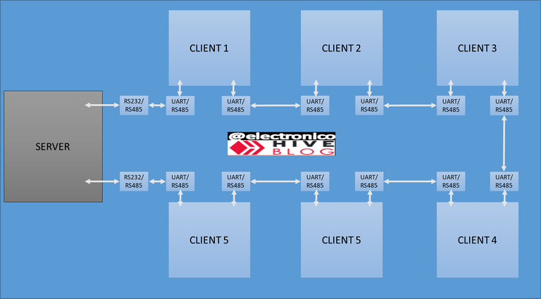
We can call this structure "physical layer" because it determines the physical connections within the protocol, each small box represents a converter between one mode and another and each large box represents a device, in this case SERVER represents the computer or master card designed to take control of all devices.
Now we only need to go into the details of how to connect and configure the adapters and how to adapt the program in the microcontroller to work in the RS485 protocol, but we will leave that pending for the next article, meanwhile I say goodbye thanking you for reading my article and being attentive to your comments.
A esta estructura lo podemos llamar "capa física" porque determina las conexiones físicas dentro del protocolo, cada caja pequeña representa un conversor entre un modo y otro y cada caja grande representa un dispositivo, para este caso SERVER representa el ordenador o tarjeta maestra destinada a llevar el control de todos los dispositivos.
Ahora solo nos falta entrar en los detalles de como conectar y configurar los adaptadores y cómo adaptar el programa en el microcontrolador para que funcione en el protocolo RS485, pero eso lo dejaremos pendiente para el siguiente artículo, mientras tanto me despido agradeciéndote por haber leido mi articulo y quedando atento a tus comentarios.

Thanks for your contribution to the STEMsocial community. Feel free to join us on discord to get to know the rest of us!
Please consider delegating to the @stemsocial account (85% of the curation rewards are returned).
You may also include @stemsocial as a beneficiary of the rewards of this post to get a stronger support.
thank you

Yay! 🤗
Your content has been boosted with Ecency Points, by @electronico.
Use Ecency daily to boost your growth on platform!
Support Ecency
Vote for new Proposal
Delegate HP and earn more
thank you

Congratulations your publication has been chosen among the best of the day.
KEEP CREATING GOOD CONTENT.
thank you so much!
Congratulations @electronico! You have completed the following achievement on the Hive blockchain And have been rewarded with New badge(s)
Your next target is to reach 4000 upvotes.
You can view your badges on your board and compare yourself to others in the Ranking
If you no longer want to receive notifications, reply to this comment with the word
STOPCheck out our last posts:
Congratulations @electronico! You received a personal badge!
Wait until the end of Power Up Day to find out the size of your Power-Bee.
May the Hive Power be with you!
You can view your badges on your board and compare yourself to others in the Ranking
Check out our last posts:
Congratulations @electronico! You received a personal badge!
Participate in the next Power Up Day and try to power-up more HIVE to get a bigger Power-Bee.
May the Hive Power be with you!
You can view your badges on your board and compare yourself to others in the Ranking
Check out our last posts:
شكرا لي دعمك لنا
Thank you very much
🤗