Introduction to electronic filters EN/ES
Filters are so common that we use them in every system we design, be it mechanical, hydraulic, pneumatic, even we ourselves carry a dust filter in our noses as a matter of course.
No matter what type of process it is, the function of a filter will always be the same: to prevent unwanted elements from reaching certain parts of the process.
But depending on the process the type of filter and its manufacture may be completely different and even if the function is the same the method of making it and the materials used may not even have anything in common.
Since we have touched so many topics and our blog is dedicated to the field of engineering and electronic systems I think it would not be too much to inquire about this topic and for that I have prepared this introduction hoping that it can pave a comfortable way to less experts on the subject.
Los filtros son tan comunes que los usamos en todos los sistemas que diseñamos, sean mecanicos, hidraulicos, neumaticos incluso nosotros mismos llevamos un filtro de polvo en nuestras narices como algo natural.
Sin importar que tipo de proceso sea la función de un filtro siempre sera la misma: impedir que elementos no deseados lleguen a ciertos lugares del proceso.
Pero segun sea el proceso el tipo de filtro y su fabricación pueden ser completamente distintos y aunque la función sea la misma el método para hacerlo y los materiales usados pueden incluso no tener nada en común.
Ya que hemos tocado tantos temas y nuestro blog está dedicado al campo de la ingeniería y sistemas electrónicos creo que no estaria demas que indaguemos sobre este tema y para ello he preparado esta introducción esperando que pueda preparar un camino cómodo a los menos expertos en el tema.
 Pixabay
The truth is that I could fill many paragraphs pointing out some filters that I am sure you have come across sometime, water filter, dust, fuel. Have you ever used sunglasses? well they are light filters 😉.
Let's think for a moment in an electronic system or design of those we have seen in the blog, if we consider an electric current will be accompanied by other elements such as voltage, frequency, phase, waveform, signal, energy, heat, electric field, magnetic field among many others.
Now it is worth asking ourselves why do I need a filter in an electronic system? What element or elements do I need to eliminate from a system and how can I implement a filter that takes care of it?
Lo cierto es que podría llenar muchos párrafos señalando algunos filtros con los que estoy seguro te habrás topado alguna vez, filtro de agua, polvo, combustible. ¿Has usado alguna vez gafas de sol? pues son filtros de luz 😉.
Pensemos por un momento en un sistema electrónico o diseño de los que hemos visto en el blog, si consideramos una corriente eléctrica vendrá acompañada de otros elementos como voltaje, frecuencia, fase, forma de onda, señal, energía, calor, campo eléctrico, campo magnético entre muchos otros.
Ahora vale la pena preguntarnos ¿Para qué necesito un filtro en un sistema electrónico? ¿Que elemento o elementos necesito eliminar de un sistema y cómo puedo implementar un filtro que se encargue de hacerlo?
 Pixabay
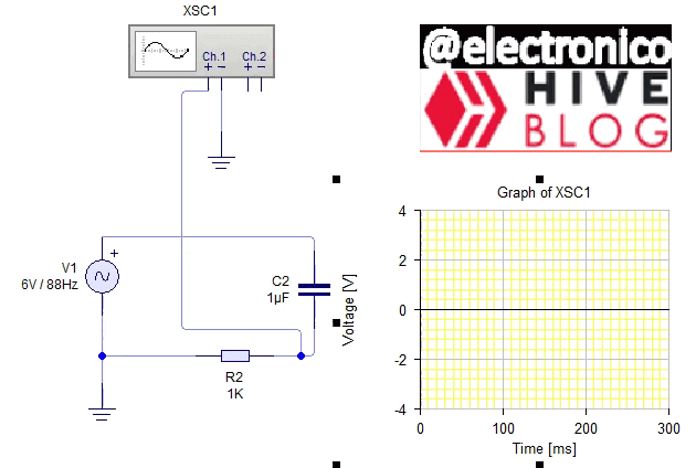
We already know that an electronic circuit can work with direct current and alternating current, direct current lacks some properties that alternating current has, such as frequency for example.
A capacitor is a component composed of two plates that have no physical contact with each other, so when used in a DC circuit the capacitor will act as an open circuit, although their plates will be charged with the voltage of the source will never circulate direct current through the capacitor.
Ya sabemos que un circuito electrónico puede trabajar con corriente continua y corriente alterna, la corriente continua carece de algunas propiedades que si presenta la corriente alterna, como la frecuencia por ejemplo.
Un capacitor es un componente compuesto por dos placas que no tienen contacto físico entre sí, así que al usarlos en un circuito DC el capacitor actuará como un circuito abierto, aunque sus placas se cargarán con el voltaje de la fuente nunca va a circular corriente continua a través del capacitor.

We can observe that the voltmeter is measuring a voltage across the capacitor, however there is no current flow, the LED has been placed in series to the capacitor to reflect this fact, also the color of the lines clearly indicates this and the voltage across the resistor with respect to ground is zero.
If we change the DC voltage by an AC voltage the circuit changes its behavior, now the variable electric field in the capacitor will allow a current flow through the capacitor that will depend on the rate of change.
Put in a simpler way the capacitor will have a resistive behavior to the passage of current that will be inversely proportional to the frequency of the voltage at its ends. This is expressed as XC=1/(wc)
Where XC is the impedance in Ohms, w is the pulsed frequency or 2pif where f is the frequency in hertz.
Podemos observar que el voltímetro está midiendo un voltaje en el capacitor, sin embargo no hay flujo de corriente, el LED ha sido colocado en serie al capacitor para reflejar este hecho, además el color de las líneas lo indica con claridad y el voltaje en la resistencia respecto a tierra es cero.
Si cambiamos el voltaje DC por un AC el circuito cambia su comportamiento, ahora el campo eléctrico variable en el capacitor permitirá un flujo de corriente a través del capacitor que dependerá de la tasa de variación.
Dicho de una manera más sencilla el capacitor tendrá un comportamiento resistivo al paso de la corriente que sera inversamente proporcional a la frecuencia del voltaje en sus extremos. Esto se expresa como XC=1/(wc)
Donde XC es la impedancia en Ohms, w es la frecuencia pulsátil o 2pif siendo f la frecuencia en hertz.
Since a capacitive impedance will be higher the lower the frequency, it is logical to think that in a DC circuit (zero frequency) a capacitor will act as a resistor of infinite value in which case it will not allow the passage of current.
Now that we have seen this phenomenon that occurs inversely in inductors (XL=wL) we can use these passive components as filters, in this case the element to filter is the frequency.
It means that you can generate a signal at the frequency I want to use and then create filters to attenuate or eliminate the rest of the frequencies, so you can also send multiple signals through the same channel and each receiver can choose through filters which signal to receive as long as the signals do not interfere with each other at the same frequency.
But none of this is new, it is the way we choose which FM radio station to tune or choose TV channels.
This has only been the introduction and I have tried to make it as simple as possible so that it can be easily understood, however if you still have questions or suggestions I remain attentive to the comments section.
See you in the next installment!
Ya que una impedancia capacitiva sera mayor cuanto menor sea la frecuencia es lógico pensar que en un circuito DC (Frecuencia cero) un capacitor actuará como una resistencia de valor infinito en cuyo caso no permitirá el paso de corriente.
Ahora que hemos visto este fenómeno que ocurre de forma inversa en los inductores (XL=wL) podemos usar estos componentes pasivos como filtros, en este caso el elemento a filtrar es la frecuencia.
Significa que se puede generar una señal a la frecuencia que quiero usar y luego crear filtros para que atenúen o eliminen el resto de las frecuencias, así se puede además enviar varias señales por un mismo canal y cada receptor puede elegir mediante filtros cuál señal desea recibir siempre y cuando las señales no interfieran entre ellas a la misma frecuencia.
Pero nada de esto es nuevo, es la forma como escogemos qué emisora de radio FM sintonizar o escogemos canales de TV.
Esta solo ha sido la introducción y he intentado hacerla lo más simple posible para que se pueda comprender con facilidad, sin embargo si aún tienes dudas o sugerencias quedo atento a la sección de comentarios.
Nos leemos en la siguiente entrega.!

Post manually reviewed. 😊
Yay! 🤗
Your content has been boosted with Ecency Points, by @electronico.
Use Ecency daily to boost your growth on platform!
Support Ecency
Vote for new Proposal
Delegate HP and earn more
Excelente artículo sobre el comportamiento de los filtros tanto en DC como en AC. otro ejemplo de su uso podría ser el de la reducción de rizo con capacitores electrolíticos cuando se utilizan de forma posterior a un rectificador para que una señal AC se vaya convirtiendo en una DC.
Muchas gracias, oh por supuesto.! existen muchas aplicaciones, esta solo fue la introducción a una serie en la cual nos vamos a sumergir cada vez más profundo. Esté atento si el tema es de su interés!!
Thanks for your contribution to the STEMsocial community. Feel free to join us on discord to get to know the rest of us!
Please consider delegating to the @stemsocial account (85% of the curation rewards are returned).
You may also include @stemsocial as a beneficiary of the rewards of this post to get a stronger support.