Explaining the triple bridge EN/ES
One of the most difficult stages (in my opinion) when trying to understand the control for brushless motors is the three-phase bridge, I guess that's because of the number of interactions that must occur at this stage and the precise order in which they must occur.
But don't let me intimidate you so soon with my words, in this article I will explain it so clear and illustrated that it will be difficult not to understand it after having read it carefully.
On the other hand we have already laid the foundations in the article Introduction to DC motor control EN/ES, specifically in what we call H-bridge because a triple bridge is nothing more than an H-bridge to which we have added two extra switches.
Una de las etapas que mayor dificultad presenta (a mi parecer) al momento de intentar comprender el control para motores brushless es el puente trifásico, supongo que eso se debe a la cantidad de interacciones que deben ocurrir en esta etapa y el orden preciso en el que deben ocurrir.
Pero no dejes te dejes intimidar tan pronto con mis palabras, en este artículo lo explicaré tan claro e ilustrado que lo difícil será no comprenderlo luego de haber leído con atención.
Por otro lado ya hemos asentado los cimientos en el artículo Introduction to DC motor control EN/ES, específicamente en lo que denominamos Puente H ya que un puente triple no es otra cosa que un puente H al que hemos añadido dos conmutadores extra.
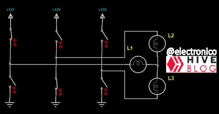
Immediately we can notice that the load is not 1 (dc motor that we use for the H bridge) but 3, these 3 loads in which I have placed lamps for illustrative purposes represent the 3 coils of a brushless motor, although a brushless motor is a single component we can not fully understand it by looking at it like that, before we must consider each of the 3 coils as a load and the activation of each one with reference to the others.
But let's postpone those interactions for a few paragraphs later, for now I want to review an important characteristic of the coils and that is their polarization. A coil can be polarized in two ways, we have already seen an example of this in Introduction to DC motor control EN/ES
De inmediato podemos notar que la carga no es 1 (motor dc que usamos para el puente H) sino 3, estas 3 cargas en las que he colocado lámparas con fines ilustrativos representan las 3 bobinas de un motor brushless, aunque un motor brushless es un solo componente no podremos comprenderlo del todo mirándolo así, antes debemos considerar cada una de las 3 bobinas como una carga y la activación de cada una con referencia a las demás.
Pero vamos a posponer esas interacciones para unos párrafos más adelante, por ahora quiero que repasemos una característica importante de las bobinas y es su polarización. Una bobina se puede polarizar de dos formas, ya vimos un ejemplo de esto en Introduction to DC motor control EN/ES
If we consider the motor connection terminals as bits we can say that there are two combinations that activate it, namely 10 and 01 (the same applies to the coils), but ... it is important to note that although both combinations energize the motor / coil the result is not similar and this we can notice in the example of the motor with the change of direction of rotation, this implies that the direction of the current that is passing through the coil is reversed between a combination and another therefore so is the electromagnetic field generated.
Having clarified the above it is necessary to go back one step to the article Controlling a brushless motor with 3 Mosfets EN/ES. to notice that the coils are connected in a star configuration (this is not true when the motor is running, it will be explained shortly) and that in our first start-up we connect the positive to the common point and the other end of each coil to ground.
Si consideramos los terminales de conección del motor como bits podemos decir que hay dos combinaciones que lo activan, a saber, 10 y 01 (lo mismo aplica a las bobinas), pero... es importante destacar que aunque ambas combinaciones energizan el motor/bobina el resultado no es similar y esto lo podemos notar en el ejemplo del motor con el cambio del sentido de giro, eso implica que la dirección de la corriente que está pasando por la bobina es inversa entre una combinación y otra por lo tanto también lo es el campo electromagnético generado.
Aclarado lo anterior es necesario volver un paso atrás al artículo Controlling a brushless motor with 3 Mosfets EN/ES. para notar que las bobinas están conectadas en una configuración estrella (esto no es cierto cuando el motor está en marcha, se explicará en breve) y que en nuestra primera puestá en marcha conectamos el positivo al punto comun y el otro extremo de cada boboina a tierra.
From the above we can say that each coil is energized with respect to ground in only one direction, in other words, if instead of coils we had connected dc motors with brushes we would have seen that every time they were energized they would rotate in the same direction.
By means of the triple bridge we can apply both directions to each coil which will give us some advantages among which we will highlight now a greater force in the motor, the correct way is to activate two coils simultaneously but one in inverted sense with respect to the other. This is achieved by making the current enters through one and exits through the other, for this we do not connect the common point to Vcc or Vss.
De lo anterior podemos decir que cada bobina es energizada respecto a tierra en un solo sentido, dicho de otra forma, si en lugar de bobinas hubiéramos conectado motores dc con escobillas hubiéramos visto que cada vez que eran energizados giraban en la misma dirección.
Mediante el puente triple podemos aplicar ambas direcciones a cada bobina lo que nos dará algunas ventajas entre las que resaltaremos ahora una mayor fuerza en el motor, la forma correcta es activar dos bobinas de forma simultánea pero una en sentido invertido respecto a la otra. Esto se logra haciendo que la corriente entre por una y salga por la otra, para ello no conectamos el punto común a Vcc ni a Vss.

If we take as reference the common point we will notice that a current enters from a coil and leaves towards another coil, for convenience we will say that the one that enters is positive and the one that leaves is negative (Kirchhoff's Law of the currents) and we will note this for a future use.
Since the current is inverse in the two activated coils we can assume that the electromagnetic fields are also inverse, if instead of coils we would have DC motors with brushes we would see them rotating in opposite directions.
The triple bridge will then allow us 6 possible combinations for a correct rotation. When you look "out there" you will find that the correct combination for one direction is 110 101 011 110 011 101. Where each bit represents one of the coils and 1 implies that it is activated.
The above combination is confusing and incomplete, while it is true that we have 3 coils (3 bits per combination) it is also true that each coil can be energized in 2 possible ways and with only 1 bit per coil we cannot determine the correct sense in which it should be energized, 2 bits are then needed for each coil where one bit represents one sense and the other the opposite sense, this will give us a combination of 6 bits.
To look at this clearly let's replace the manual switches with Mosfets transistors.
Si tomamos como referencia el punto común notaremos que una corriente entra desde una bobina y sale hacia otra bobina, por conveniencia diremos que la que entra es positiva y la que sale es negativa (Ley de las corrientes de Kirchhoff) y apuntaremos esto para un uso futuro.
Ya que la corriente es inversa en las dos bobinas activadas podemos suponer que los campos electromagnéticos también lo son, si en lugar de bobinas tuviésemos motores DC con escobillas los viésemos girar en sentidos opuestos.
El puente triple nos permitirá entonces 6 combinaciones posibles para un giro correcto. Cuando buscas "por ahí" encontrarás que la combinación correcta para un sentido es 110 101 011 110 011 101. Donde cada bit representa una de las bobinas y 1 implica que está activada.
La combinación anterior es confusa e incompleta, si bien es cierto que tenemos 3 bobinas (3 bits por combinación) también lo es que cada bobina puede ser activada de 2 formas posibles y con 1 solo bit por bobina no podemos determinar el sentido correcto en el que se debe energizar, se necesitan entonces 2 bits para cada bobina en los que un bit representa un sentido y el otro el sentido opuesto, esto nos dará una combinación de 6 bits.
Para mirar esto con claridad vamos a reemplazar los interruptores manuales por transistores Mosfets.
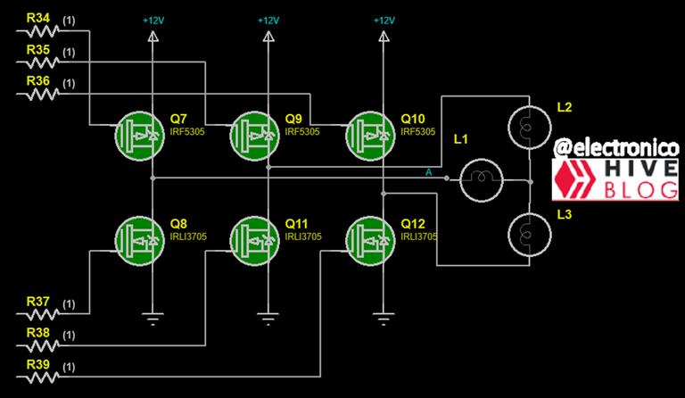
We can notice that having 6 mosfets we will need 6 switching signals (one for each one) therefore 6 bits combinations are required in each stage. Did you notice that (666) just made my skin crawl 😫.
Now let's consider each coil according to the direction of the current passing through it, then L1 will be L1p when the current has one direction and L1n when it has the opposite direction, the same will apply to all and the position of each one with respect to its associated bit will be L1pL2pL3p L1nL2nL3n, the 6 correct combinations for a direction will be: 100 010, 100 001, 010 001, 010 001, 010 100, 001 100, 010 001.
In the described combination the group of 3 on the left will mark with 1 the coil to be connected to positive and the group on the right will mark with 1 the coil to be connected to ground.
Podemos notar que al tener 6 mosfets necesitaremos 6 señales de conmutación (una para cada uno) por lo tanto se requieren combinaciones de 6 bits en cada etapa. ¿Lo notaste? (666) se me acaba de erizar la piel 😫.
Ahora vamos a considerar cada bobina segun el sentido de la corriente que la atraviesa, entonces L1 será L1p cuando la corriente tiene un sentido y L1n cuando tiene el sentido opuesto, lo mismo aplicaremos a todas y la posición de cada una respecto a su bit asociado será L1pL2pL3p L1nL2nL3n, las 6 combinaciones correctas para un sentido serán: 100 010, 100 001, 010 001, 010 100, 001 100, 010 001.
En la combinación descrita el grupo de 3 de la izquierda marcará con 1 la bobina que debe conectarse a positivo y el grupo de la derecha marcará con 1 la bobina que se debe conectar a tierra.
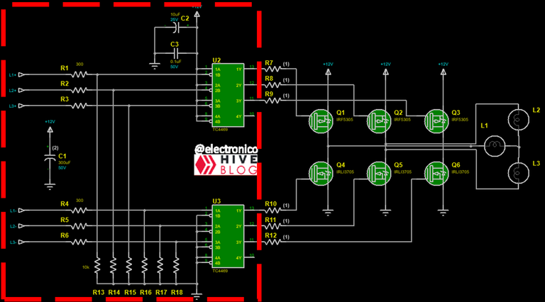
The circuit we see in the red box will facilitate the activation of the mosfets, to switch a positive voltage the P-channel mosfets are activated (with 0V), to switch a coil to ground its respective N-channel mosfet is activated (12V).
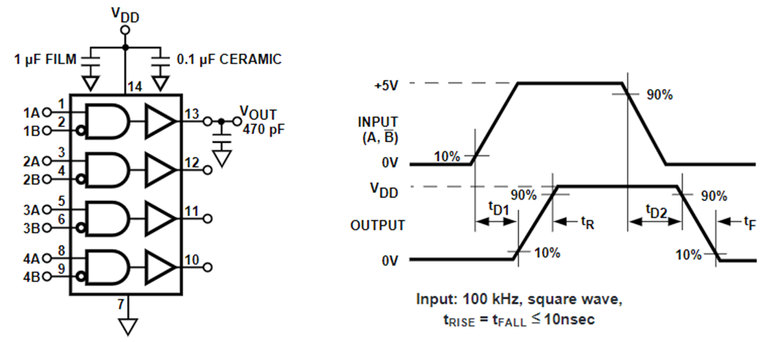
The TC4469 integrated can receive a logic voltage and convert it into a 0-12V output to switch the mosfets. Since it is an and with a negated input it can even be arranged to activate the P-channel mosfets with a high signal, this will help in programming.
El circuito que vemos en el cuadro rojo facilitará la activación de los mosfets, para conmutar un voltaje positivo se activan los mosfets de canal P (con 0V), para conmutar una bobina a tierra se activa su mosfet canal N respectivo (12V).
El integrado TC4469 puede recibir un voltaje lógico y convertirlo en una salida de 0-12V con los que conmutar los mosfets. Ya que es una and con una entrada negada incluso se puede hacer el arreglo para activar los mosfets canal P con una señal alta, esto ayudará en la programación.
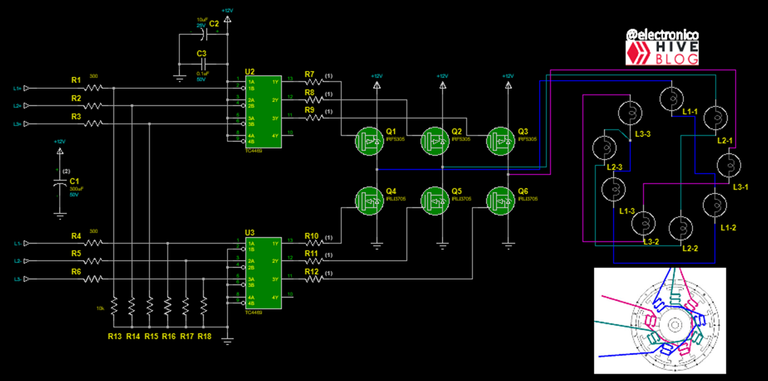
Now I want us to look at how the sequence is activated internally in the brushless motor using the triple bridge, for this instead of coils I have connected lamps, so we know that a lit lamp is equivalent to an energized coil.
Although the brushless motors have 3 coils these are distributed in circular form in different cores to create the rotating field, in the following image we will see how I have connected the lamps with 3 cores per coil and the corresponding windings in the image below.
Ahora quiero que miremos cómo se activa la secuencia internamente en el motor brushless usando el puente triple, para ello en lugar de bobinas he conectado lámparas, así sabemos que una lámpara encendida equivale a una bobina energizada.
Aunque los motores brushless tienen 3 bobinas estas se distribuyen en forma circular en distintos núcleos para crear el campo giratorio, en la siguiente imagen veremos cómo he conectado las lámparas de 3 núcleos por bobina y los embobinados correspondiente en la imagen inferior.
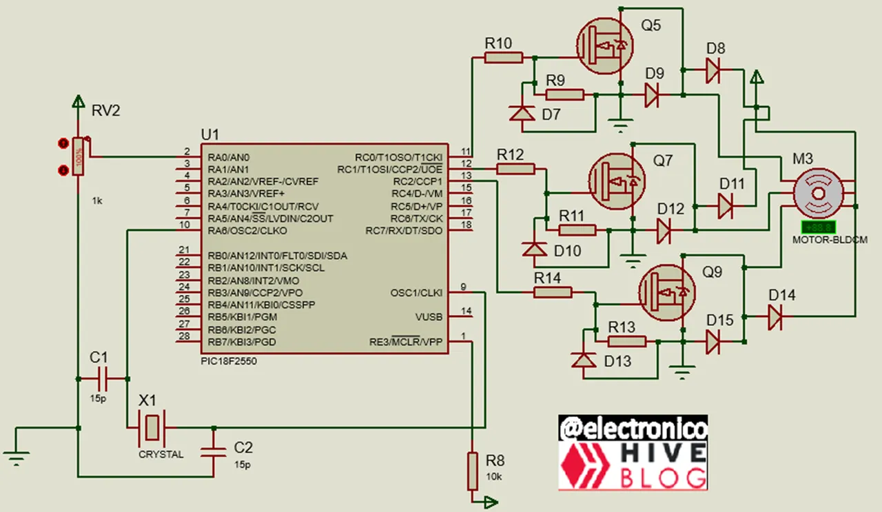
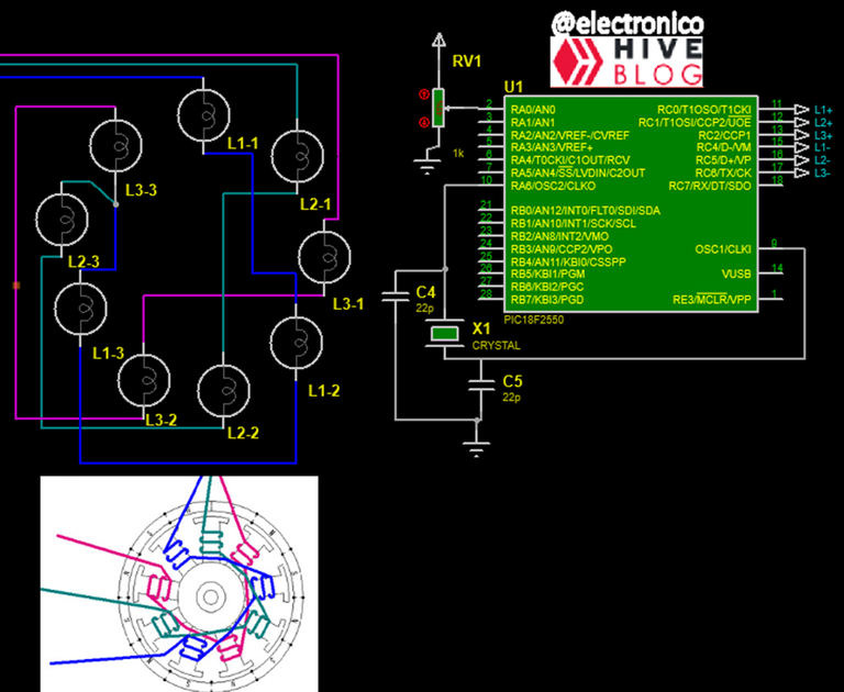
Now we add our microcontroller of turn (PIC18F2550) to excite the mosfets with the sequence indicated a few paragraphs ago.
Ahora añadimos nuestro microcontrolador de turno (PIC18F2550) para excitar los mosfets con la secuencia indicada unos párrafos atrás.
The program to load in the micro is simple, the only thing we want is to generate the correct sequence to see the behavior of the lamps and how this sequence creates the rotating field, plus of course to note how two coils are activated.
The program code will be:
El programa a cargar en el micro es sencillo, lo único que queremos es generar la secuencia correcta para ver el comportamiento de las lámparas y la forma como esta secuencia crea el campo giratorio, además por supuesto de notar la forma en que dos bobinas son activadas.
El código del programa será:
#include <18f2550.h>
#device ADC = 10
#fuses HS,NOWDT,NOPROTECT,NOLVP,PUT,CPUDIV1,NODEBUG,USBDIV,PLL5,VREGEN,NOPBADEN
#use delay(Clock=20000000)
#use standard_io(C)
#include <map_function.c

#define L1p PIN_C0
#define L2p PIN_C1
#define L3p PIN_C2
#define L1n PIN_C4
#define L2n PIN_C5
#define L3n PIN_C6
int16 adc;
int16 speed;


void main()
{
   setup_adc_ports(AN0);
   setup_adc(adc_clock_internal);

   while(true)
   {
    set_adc_channel(0);
    delay_us(20);
    adc = read_adc();
    speed=map(adc, 0, 1023, 2000, 46);
    delay_ms(speed);

    output_high(L1p);
    output_low(L2p);
    output_low(L3p);
    output_low(L1n);
    output_high(L2n);
    output_low(L3n);
    delay_ms(speed);

    output_high(L1p);
    output_low(L2p);
    output_low(L3p);
    output_low(L1n);
    output_low(L2n);
    output_high(L3n);
    delay_ms(speed);

    output_low(L1p);
    output_high(L2p);
    output_low(L3p);
    output_low(L1n);
    output_low(L2n);
    output_high(L3n);
    delay_ms(speed);

    output_low(L1p);
    output_high(L2p);
    output_low(L3p);
    output_high(L1n);
    output_low(L2n);
    output_low(L3n);
    delay_ms(speed);

    output_low(L1p);
    output_low(L2p);
    output_high(L3p);
    output_high(L1n);
    output_low(L2n);
    output_low(L3n);
    delay_ms(speed);

    output_low(L1p);
    output_low(L2p);
    output_high(L3p);
    output_low(L1n);
    output_high(L2n);
    output_low(L3n);
    delay_ms(speed);
  }
}
Now let's see in the following animation how the whole circuit works together.
Ahora veamos en la siguiente animación como trabaja todo el circuito junto.
And finally we detail in a single animation how the 6 sequences are generated inside the brushless motor with the triple bridge.
Y finalmente detallamos en una sola animación cómo se generan las 6 secuencias dentro del motor brushless con el puente triple.
Dang, I didn't expect the article to be so long for me... hope you enjoyed it. 😄
Rayos! no esperaba que el artículo me quedase tan largo... espero lo hayas disfrutado. 😄
If you want to give an extra boost to the blog with a donation you can send it to the addresses:
Si quieres darle un impulso extra al blog con una donación puedes enviarla a las direcciones:
BEP-20: 0x5Aee5e3e3ED3203e77eF0d8Bb3E3a420E5229Ce0
ERC-20: 0x5Aee5e3e3ED3203e77eF0d8Bb3E3a420E5229Ce0
Arbitrum One: 0x5Aee5e3e3ED3203e77eF0d8Bb3E3a420E5229Ce0
Polygon: 0x5Aee5e3e3ED3203e77eF0d8Bb3E3a420E5229Ce0
Avalanche: 0x5Aee5e3e3ED3203e77eF0d8Bb3E3a420E5229Ce0
Thanks for your contribution to the STEMsocial community. Feel free to join us on discord to get to know the rest of us!
Please consider delegating to the @stemsocial account (85% of the curation rewards are returned).
Thanks for including @stemsocial as a beneficiary, which gives you stronger support.