Controlling a brushless motor with 3 Mosfets EN/ES.
Now that we've looked at some brushless motor theory and established some safety considerations we're ready for our first real test with a brushless motor.
Ahora que vimos un poco de teoría sobre motores brushless y establecimos algunas consideraciones de seguridad estamos listos para nuestra primera prueba real con un motor brushless.
One of the features that makes a brushless motor stand out is its ability to work at several tens of thousands of RPMs, that speed makes them a favorite in drone construction, when used in computer disk drives however the speed is tried to be kept at 7200 RPMs in most cases.
Now let's consider their use in cars or electric bikes, I wouldn't want to be on an electric bike whose wheel spins at 7200RPMs or more 🤣.
The complexity is not only in producing the spin, but also in controlling the speed of the spin. In today's practice we will set up an open loop circuit that only requires 3 mosfets and a microcontroller to set up control for illustrative purposes.
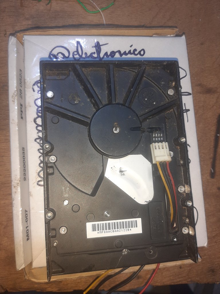
To do this I have taken one that is attached to the casing of a storage unit (recycled and dusty) popularly known as hard disk, since the electronic card that controls this motor has been removed by default we will connect the 4 wires (3 coils plus common) to take them to our control circuit.
Una de las características que hace resaltar un motor brushless es su capacidad para trabajar a varias decenas de miles de RPMs, esa velocidad hace que sean los favoritos en la construcción de drones, cuando se usan en unidades de discos para ordenadores sin embargo la velocidad se intenta mantener en 7200 RPMs en la mayoría de los casos.
Ahora consideremos su uso en coches o bicicletas eléctricas, no quisiera estar sobre una bicicleta eléctrica cuya rueda gire a 7200RPMs o más 🤣.
La complejidad no solo está en producir el giro sino, además, en controlar la velocidad del mismo. En la práctica de hoy estableceremos un circuito de bucle abierto que solo requiere de 3 mosfets y un microcontrolador para establecer un control con fines ilustrativos.
Para ello he sacado uno que va pegado a la carcaza de una unidad de almacenamiento (reciclada y polvorienta) conocida popularmente como Disco Duro, ya que se ha retirado la tarjeta electrónica que controla este motor por defecto conectaremos los 4 cables (3 bobinas más común) para llevarlos a nuestro circuito de control.
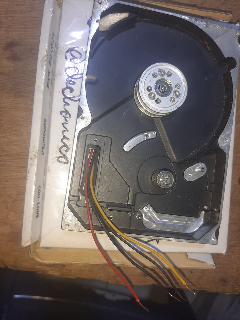
We remove the ends of the cables connected at the front and in this way we can make the connections and observe the behavior of the motor in operation.
Extraemos las puntas de los cables conectados por la parte delantera y de esa forma podremos hacer las conexiones y observar el comportamiento del motor en funcionamiento.
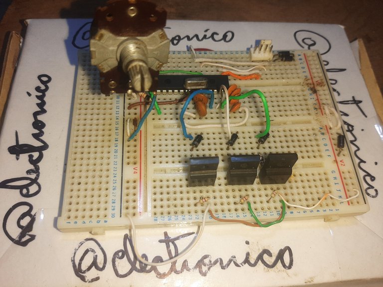
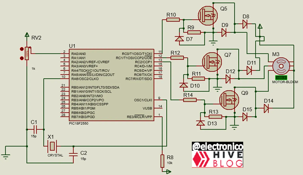
To control this man we are going to use our PIC18F2550, with 3 mosfets accompanied by the protection components described above.
With an ADC we will be able to adjust the switching times of the coils which should affect the speed of the motor.
Para controlar a este señor vamos a usar nuestro PIC18F2550, con 3 mosfets acompañados de los componentes de protección descritos anteriormente.
Con un ADC podremos ajustar los tiempos de conmutación de las bobinas lo cual debería afectar la velocidad de giro del motor.
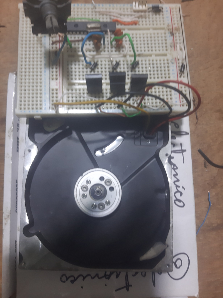
Finally we connect our motor to the breadboard as agreed in the circuit where the protection components are implemented.
Finalmente conectamos nuestro motor a la protoboard según convenimos en el circuito donde se implementan los componentes de protecciones.
The physical connection of all interconnected components to each other then takes on the following appearance:
La conexión física de todos los componentes interconectados entre sí toma entonces la siguiente apariencia:
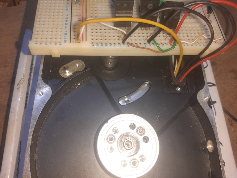
And with this we have completed all the physical part, now comes the exciting part, the one where we write in a code our desire about the behavior of the motor. Let's program it!
We must take into account a certain activation sequence because otherwise our motor will do anything but turn!
The correct sequence to the right if we consider the ABC coils in a logic where 1 is a value of activation and 0 of deactivation we have: 100 110 010 011 001 101.
If we want it to rotate in the opposite direction the sequence is: 101 001 011 010 110 100.
We will establish the first sequence with the following program for our PIC18F2550:
Y con esto tenemos completada toda la parte física, ahora viene la parte emocionante, esa en la que escribimos en un código nuestro deseo sobre el comportamiento del motor. ¡Vamos a programarlo!
Debemos tomar en cuenta cierta secuencia de activación porque de lo contrario ¡nuestro motor hará cualquier cosa menos girar.!
La secuencia correcta hacia la derecha si consideramos las bobinas ABC en una lógica donde 1 es un valor de activación y 0 de desactivación tenemos: 100 110 010 011 001 101.
Si queremos que gire en sentido contrario la secuencia es: 101 001 011 010 110 100.
Estableceremos la primera secuencia con el siguiente programa para nuestro PIC18F2550:
#include <18f2550.h>
#device ADC = 10
#fuses HS,NOWDT,NOPROTECT,NOLVP,PUT,CPUDIV1,NODEBUG,USBDIV,PLL5,VREGEN,NOPBADEN
#use delay(Clock=20000000)
#use standard_io(C)
#include <map_function.c

#define L1 PIN_C0
#define L2 PIN_C1
#define L3 PIN_C2
We have set L1, L2 and L3 as the ABC coils respectively. We will set a variable to capture the ADC value and another one to take the value of the time that each coil is active, remember that long times can damage the coil.
Hemos establecido L1, L2 y L3 como las bobinas ABC respectivamente. Estableceremos una variable para capturar el valor del ADC y otra para llevar el valor del tiempo que dura activa cada bobina, recordemos que tiempos largos pueden dañar la bobina.
int16 adc;
int16 speed;
Then if we are going to use an ADC we configure it to play with the potentiometer, we will use the map function to adapt the ADC value to the time range that we will allow between each activation signal.
Luego si vamos a usar un ADC lo configuramos para jugar con el potenciómetro, usaremos la función map para adaptar el valor del ADC al rango de tiempo que permitiremos entre cada señal de activación.
void main()
{
   setup_adc_ports(AN0);
   setup_adc(adc_clock_internal);

   while(true)
   {
    set_adc_channel(0);
    delay_us(20);
    adc = read_adc();
    speed=map(adc, 0, 1023, 30000, 800);
Now we just write the activation sequence in the order described above, between each interval we include a delay whose value corresponds to the speed variable associated to the ADC values, thus determining the time between each change.
Ahora solo escribimos la secuencia de activación en el orden descrito unos párrafos arriba, entre cada intervalo incluimos un retardo cuyo valor se corresponde a la variable speed asociada a los valores del ADC, así determinamos el tiempo entre cada cambio.
    output_low(L1); //0
    output_low(L2); //0
    output_low(L3); //0
    delay_us(speed);
    output_high(L1); //1
    output_low(L2);  //0
    output_low(L3); //0
    delay_us(speed);
    output_high(L1); //1
    output_high(L2); //1
    output_low(L3); //0
    delay_us(speed);
    output_low(L1); //0
    output_high(L2); //1
    output_low(L3); //0
    delay_us(speed);
    output_low(L1); //0
    output_high(L2); //1
    output_high(L3); //1
    delay_us(speed);
    output_low(L1); //0
    output_low(L2); //0
    output_high(L3); //1
    delay_us(speed);
    output_high(L1); //1
    output_low(L2); //0
    output_high(L3); //1
    delay_us(speed);
  }
}
With all this we can now see our contraption working with a simple circuit and a simple program, believe me, it won't always be so easy with this kind of motors 😎.
Con todo esto ya podemos ver nuestro artilugio funcionando con un circuito sencillo y un programa sencillo, creeme, no siempre será tan fácil con este tipo de motores 😎.
If you want to give an extra boost to the blog with a donation you can send it to the addresses:
Si quieres darle un impulso extra al blog con una donación puedes enviarla a las direcciones:
BEP-20: 0x5Aee5e3e3ED3203e77eF0d8Bb3E3a420E5229Ce0
ERC-20: 0x5Aee5e3e3ED3203e77eF0d8Bb3E3a420E5229Ce0
Arbitrum One: 0x5Aee5e3e3ED3203e77eF0d8Bb3E3a420E5229Ce0
Polygon: 0x5Aee5e3e3ED3203e77eF0d8Bb3E3a420E5229Ce0
Avalanche: 0x5Aee5e3e3ED3203e77eF0d8Bb3E3a420E5229Ce0
It would have been nice if you had actually constructed the motor from scratch or did you ?
I used to be a fan of these kind of DIY projects, especially the electromagnetic kinds in the past. There's this kind of joy I get when I build from scratch, including trying to introduce new ideas. Unfortunately, for some reasons I have not quite understood, I lost interest. 😁
Great post by the way. 👍
Sure, it would have been more exciting but it would have taken me more time than I usually have for these things. Anyway the main purpose I'm looking for is the understanding about electronic control systems, maybe in the future when I'm a little less loaded we'll build some engines from scratch....
When we abandon the practice we usually lose interest, in fact it is one of the reasons why I created the blog, I can share knowledge while staying active in the area.
Thanks my friend, it pleases me very much to read comments like yours in my articles.
Thanks for your contribution to the STEMsocial community. Feel free to join us on discord to get to know the rest of us!
Please consider delegating to the @stemsocial account (85% of the curation rewards are returned).
Thanks for including @stemsocial as a beneficiary, which gives you stronger support.
WOW, what an amazing tutorial, you've spend some time on this project obviously, nice job! I do a lot of controls myself (and now post tips for python asI've done a lot of controls using python actually), very little with PIC processors though, but great little project, a lot to learn. Following...
I should try this because I should have all of this stuff.... how do I add a throttle?