Component Electronics: The SCR EN/ES
At this point it has already been demonstrated indisputably the capabilities of microcontrollers to design almost any control system, however and as has been expressed in previous articles, it would be illusory to think that this is enough.
In the control stage we establish the logic and parameters by which a system acts based on the input signals to produce output signals, if our systems are low power perhaps 5VDC voltages and small currents delivered by the microcontroller may be sufficient and some cases.
Even if it is possible to use the microcontroller to supply the output power in circuits that are not so power demanding I would not recommend to do it since it was not designed for this purpose, instead we could use relays or transistors as we saw in the article BJT Transistor As Switch.
But there comes a power limit in which the transistors are no longer useful, this is where an electronic innovation comes into play for its time and is the component that will open the door for control systems based on medium and high power components, I mean the SCR.
En este punto ya ha quedado demostrada de forma indiscutible las capacidades de los microcontroladores para diseñar casi cualquier sistema de control, sin embargo y como se ha expresado en artículos anteriores, sería iluso pensar que con eso es suficiente.
En la etapa de control establecemos la lógica y parámetros mediante los cuales actúa un sistema basado en las señales de entrada para producir señales de salida, si nuestros sistemas son de baja potencia tal vez los voltajes de 5VDC y la pequeñas corrientes que entrega el microcontrolador puedan ser suficientes y algunos casos.
Aun cuando sea posible usar el microcontrolador para suministrar la potencia de salida en circuitos que no son tan exigentes en cuanto a potencia no recomendaría hacerlo ya que no fue diseñado para este propósito, en su lugar podríamos usar relés o transistores como vimos en el artículo Transistor BJT Como conmutador.
Pero llega un límite de potencia en el que los transistores dejan de ser útiles, es aquí donde entra en juego una innovación electrónica para su época y es el componente que nos abrirá la puerta para los sistemas de control basados en componentes de media y alta potencia, me refiero al SCR.
Principle of operation |
|---|
We need to advance in the design of our systems to the actuator stage, most of them handle voltages and powers in magnitudes unquestionably harmful to the microcontroller and even the transistors, a semiconductor device appeared in 1960 to solve this problem.
More than 60 years in existence I am sure there must be a lot of theoretical and practical material everywhere to learn about it and one might even think that there are already components that can surely do the same function with much more efficiency and both things are true which brings us to the important question: What are we doing writing about this?
For this we can justify ourselves with two compelling reasons, that apparently the older components are easier to explain for the later understanding of the more advanced ones and that although this component has gray hairs, it is still useful for simple projects in which you do not want to make large investments.
Although my main reason is the ease with which you can understand the operation of this component, if we consider a transistor in switch mode we will always have a small activation current entering through one of its terminals to control a larger current entering a second terminal and out a third, in these cases the activation terminal usually has sufficient electronic isolation from the others to protect the control source.
The easiest way I can think of to explain an SCR is to consider that we have a common diode to which we add a third terminal by which we decide from when the diode will conduct (when it is directly polarized).
Necesitamos avanzar en el diseño de nuestros sistemas a la etapa de actuadores, la mayoría de ellos manejan tensiones y potencias en magnitudes indiscutiblemente dañinas para el microcontrolador e incluso los transistores, un dispositivo semiconductor apareció en 1960 para solucionar este problema.
Más de 60 años existiendo estoy seguro que debe haber mucho material teorico y practico en todo lugar para aprender sobre el e incluso uno podría pensar que ya hay componentes que seguramente pueden hacer la misma función con mucha más eficiencia y ambas cosas son ciertas lo que nos lleva a la pregunta importante ¿Qué hacemos escribiendo sobre esto?
Para esto podemos justificarnos con dos razones contundentes, que al parecer los componentes más antiguos son más fáciles de explicar para la posterior comprensión de los más avanzados y que aunque este componente tenga canas, aún sigue siendo útil para proyectos sencillos en los que no se quiere hacer grandes inversiones.
Aunque mi razón principal es la facilidad con que se puede entender el funcionamiento de este componente, si consideramos un transistor en modo conmutador siempre tendremos una pequeña corriente de activación que entra por uno de sus terminales para controlar una corriente mayor que entra por un segundo terminal y sale por un tercero, en estos casos el terminal de activación suele tener suficiente aislamiento electrónico de los demás para proteger la fuente de control.
La forma más fácil que se me ocurre para explicar un SCR es considerar que tenemos un diodo común al cual añadimos un tercer terminal mediante el cual decidimos a partir de cuando el diodo conducirá (cuando esté polarizado en forma directa).
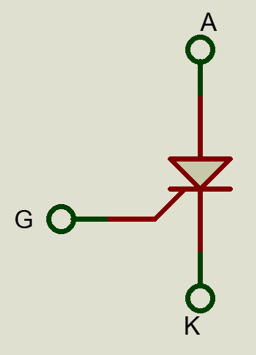
We could also make an analog with a transistor in which this third terminal (G) can be considered as the base because a small current there can lead the component to saturation but it would be incorrect because once there has been an activation pulse on the base or gate will not need to remain present to keep the component in conduction.
In other words, no voltage level is needed at the gate to maintain conduction, only a pulse that activates it and once activated the component will conduct until the current through it becomes zero, and once it is zero it will not conduct until there is another pulse at the gate.
If we are operating in direct current we will need a mechanism to deactivate the SCR when we need it, in the following circuit an example is illustrated by placing a push button in parallel to the SCR, the simulation is done to demonstrate the behavior.
Tambien podriamos hacer un análogo con un transistor en el que este tercer terminal (G) puede ser considerado como la base ya que una pequeña corriente ahí puede llevar el componente a saturación pero seria incorrecto ya que una vez que se ha producido un pulso de activación en la base o puerta no hará falta que siga presente para mantener el componente en conducción.
Dicho de otra forma, no se necesita un nivel de tensión continuó en la puerta para mantener la conducción, solo un pulso que la active y una vez activado el componente conducirá hasta que la corriente que lo atraviesa se haga cero, y una vez sea cero no conducirá hasta que se produzca otro pulso en la puerta.
Si estamos operando en corriente directa se necesitará un mecanismo para desactivar el SCR cuando lo necesitemos, en el siguiente circuito se ilustra un ejemplo colocando un pulsador en paralelo al SCR, se hace la simulación para demostrar el comportamiento.
Operation in AC |
|---|
The second thing is to know at what time to produce the shot, since being a sinusoidal will be constantly crossing zero the SCR will be constantly switching to produce a power control, this control occurs because it seeks to produce a shot at a precise angle of the positive half cycle being possible to attenuate part of this and therefore decrease the output power.
Attempting an independent firing is not an easy task, the phase angle must be known at all times because if the firing signal is sent during the negative half cycle there will be no output due to the characteristics of diode that has the SCR.
To avoid the complexity of synchronism that must be present in independent trigger circuits, the same input current is usually taken as the trigger signal and the trigger angle is obtained with a variable resistor.
An SCR will need a minimum value of current in its Gate to go into conduction, if we look at an AC signal in slow motion what happens is that the voltage increases from -Vp to +Vp, as we are going to ignore the negative values we consider only the increase from zero to Vp which occurs at a 90 degree phase angle.
We can trigger the conduction for angles between 0 and 90 degrees if we set the resistive value that produces the trigger current when the voltage is at the angle we want it to trigger.
I know it may sound confusing so I explain it with numbers, suppose our Vp is 160V which also implies that at that point the phase angle is 90, we can do a simple rule of 3 to determine what voltage value corresponds to the angle we want.
If we call Ax the Angle we are looking for, Vp the peak voltage that occurs when the phase is 90 degrees and Vx the voltage present when the angle is Ax then: Vx = Ax*Vp/90
If we want an angle of 45 degrees when our VP is 160V we just replace values in the equation and we get: Vx = 45*160/90 = 80V
We can do the same for any angle we want between 0 and 90, what we do is that with Vx we use Ohm's Law to calculate the resistance that at that voltage level will produce the trigger current.
If for our case we assume a trigger current of 20mA our resistance to produce the trigger at 45 degrees with a Vp of 160V will be R=80V/20mA = 4k.
Playing with these values we can choose a potentiometer to control the power on a load in series with the SCR.
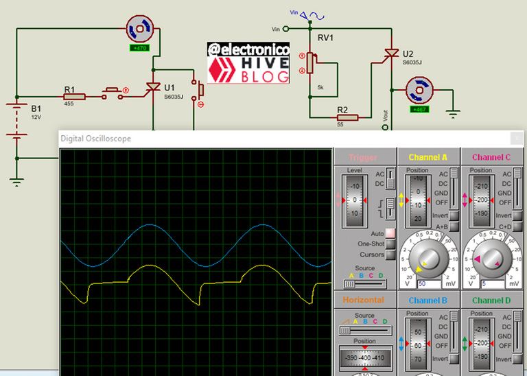
As a picture says more than a thousand words I have prepared a simulation to represent all the boring text I wrote above, we will see a blue line representing the input and a yellow line representing the output, the potentiometer will be varied and will be reflected as the output signal is modified (firing angle) and at the same time through the RPM meter of the engine we can see how the power is affected in it.
Cuando entramos en operación con AC las cosas se ponen particularmente interesantes, lo primero que debemos recordar es que nuestro SCR funciona como un Diodo, por lo tanto solo conducirá durante el semiciclo positivo y eliminará el negativo.
Lo segundo es conocer en que momento producir el disparo, ya que al ser una senoidal estará cruzando constantemente por cero el SCR estara conmutando constantemente para producir un control de potencia, este control ocurre porque se busca producir un disparo en un ángulo preciso del semiciclo positivo siendo posible atenuar parte de este y por lo tanto disminuir la potencia de salida.
Intentar un disparo independiente no es una tarea fácil, se debe conocer el ángulo de fase en todo momento ya que si se envía la señal de disparo durante el semiciclo negativo no habrá salida debido a las características de Diodo que posee el SCR.
Para evitar la complejidad del sincronismo que debe haber en circuitos de activación independientes se suele tomar la misma corriente de entrada como señal de activación y el ángulo de disparo se obtiene con una resistencia variable.
Un SCR necesitará un valor mínimo de corriente en su Gate para entrar en conducción, si miramos una señal AC en cámara lenta lo que ocurre es que el voltaje incrementa desde -Vp hasta +Vp, como vamos a ignorar los valores negativos consideramos solo el aumento desde cero a Vp lo cual ocurre en un ángulo de 90 grados de fase.
Podemos disparar la conducción para ángulos entre 0 y 90 grados si colocamos el valor resistivo que produce la corriente de activación cuando el voltaje esté en el ángulo que deseamos sea el disparo.
Se que puede sonar confuso por eso lo explico con números, supongamos que nuestro Vp es de 160V lo que también implica que en ese momento el ángulo de fase es 90, podemos hacer una regla de 3 simple para determinar qué valor de tensión corresponde al ángulo que deseamos.
Si llamamos Ax al Angulo que buscamos, Vp al voltaje pico que ocurre cuando la fase es 90 grados y Vx al voltaje presente cuando el ángulo es Ax entonces: Vx = Ax*Vp/90
Si queremos un ángulo de 45 grados cuando nuestro VP es 160V solo reemplazamos valores en la ecuación y nos queda: Vx = 45*160/90 = 80V
Podemos hacer lo mismo para cualquier ángulo que queramos entre 0 y 90, lo que hacemos es que con Vx usamos la Ley de Ohm para calcular la resistencia que con ese nivel de voltaje producirá la corriente de disparo.
Si para nuestro caso suponemos una corriente de disparo de 20mA nuestra resistencia para producir el disparo a 45 grados con un Vp de 160V será R=80V/20mA = 4k.
Jugando con estos valores se puede elegir un potenciómetro para controlar la potencia en una carga en serie con el SCR.
Como una imagen dice mas que mil palabras he preparado una simulación para representar todo el texto aburrido que escribi ahi arriba, veremos una línea azul que representa la entrada y una amarilla que representa la salida, se variara el potenciometro y se vera reflejado como se modifica la señal de salida (ángulo de disparo) y a la vez mediante el medidor de RPM del motor podremos ver como es afectada la potencia en el mismo.

Thanks for sharing a very informative content..😊Greatings to you my friend..
Thanks for your contribution to the STEMsocial community. Feel free to join us on discord to get to know the rest of us!
Please consider delegating to the @stemsocial account (85% of the curation rewards are returned).
You may also include @stemsocial as a beneficiary of the rewards of this post to get a stronger support.