Circuit for Data Acquisition from a PT100 EN/ES
Recently we addressed the temperature sensor LM34/35 in an article, one of the limitations that could be observed is that the LM34 can measure up to a maximum temperature of 150°C.
There are many processes in which the temperature variable far exceeds this value, for this reason it is considered important to address a higher range element such as a PT100 that can measure up to 800°C and even more in other improved versions.
This article explains the behavior of a PT100 and proposes a circuit through which data can be acquired and conditioned for a temperature measurement based on a PT100.
Recientemente abordamos al sensor de temperatura LM34/35 en un artículo, una de las limitaciones que se pudieron observar es que el LM34 puede medir hasta una temperatura máxima de 150°C.
Existen muchos procesos en los que la variable temperatura supera este valor con creces, por tal razón se considera importante abordar un elemento de mayor rango como lo es una PT100 que pueden medir hasta 800°C e incluso más en otras versiones mejoradas.
En este artículo se explica el comportamiento de una PT100 y se propone un circuito mediante el cual se pueden adquirir y acondicionar los datos para una medición de temperatura basada en una PT100.
 dirkhb, wikimedia commons
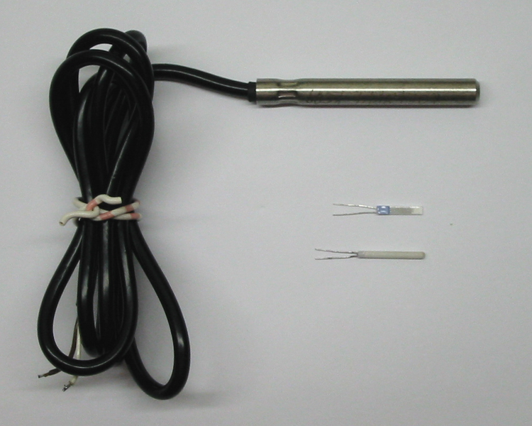
A pt100 is a platinum thermometer constructed in such a way that it presents a resistive variation in response to a temperature variation. It is designed so that at 0°C it presents a resistive value of 100 ohms (hence the name PT100).
Knowing this we can consult the table of resistive values corresponding to temperature values, or simply a graph of temperature and resistivity.
Una pt100 consiste en un termómetro construido con platino de forma tal que presenta una variación resistiva ante una variación de temperatura. Está diseñada para que a 0°C presente un valor resistivo de 100 ohmios (De ahí el nombre PT100).
Sabiendo esto podemos consultar la tabla de valores resistivos correspondiente a valores de temperatura, o simplemente una gráfica de la temperatura y a resistividad.
 Saure, WikimediaCommons
If using the table of values we can know what is the value of the temperature only by measuring the resistive value then we can also design a circuit that can present a voltage that is also proportional to the temperature variation in order to use the voltage values as signals that can be read by a controller.
Quickly we can think of a voltage divider, it would serve to use a fixed resistor with a known value and the voltage on the PT100 will be the voltage that varies in this way we get a proportional variation.
Si usando la tabla de valores podemos conocer cuál es el valor de la temperatura únicamente midiendo el valor resistivo entonces podemos también diseñar un circuito que pueda presentar un voltaje que también sea proporcional a la variación de temperatura con la finalidad de usar los valores de voltaje como señales que puedan ser leídas por un controlador.
Rápidamente podemos pensar en un divisor de tensión, serviría para usar una resistencia fija con un valor conocido y el voltaje en la PT100 será el voltaje que varíe de esta forma obtendremos una variación proporcional.
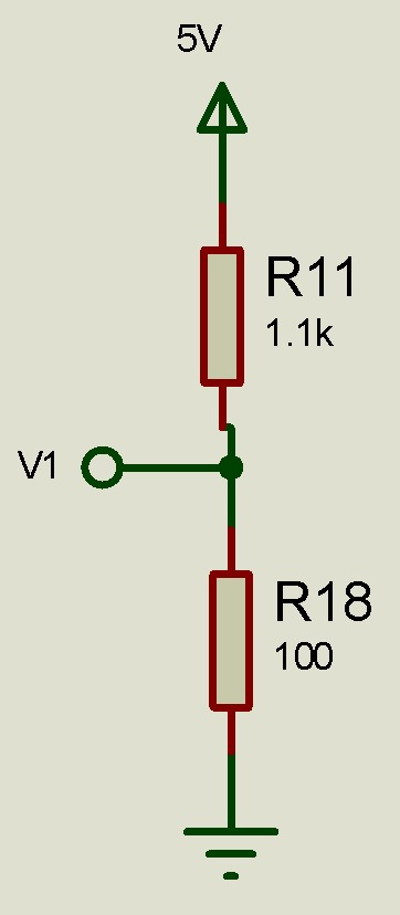
A voltage divider like the one shown can be useful, the problem is that if the temperature does not vary but the voltage source varies then V1 will also have a variation sending the wrong data.
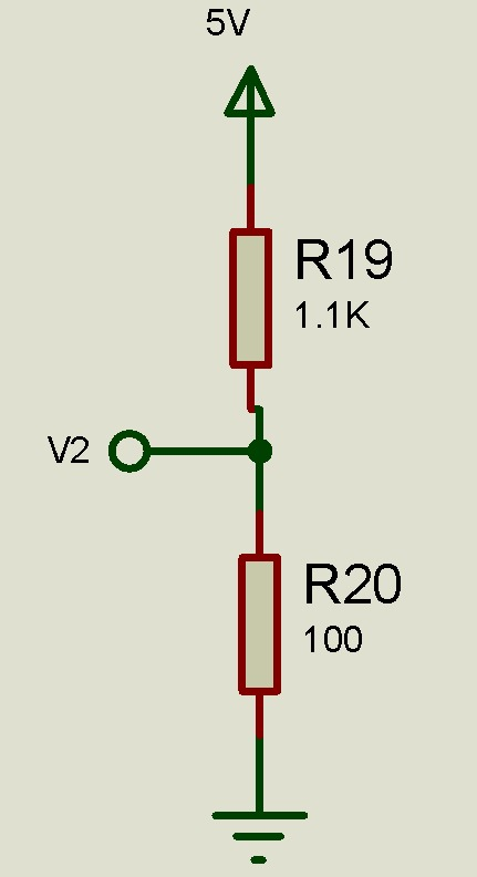
This is where a Wheatstone bridge becomes useful. To build the bridge we just need to add a second voltage divider that mirrors the first one.
Un divisor de voltaje como el mostrado puede ser útil, el problema es que si la temperatura no varía pero la fuente de voltaje varía entonces V1 tendrá también una variación enviando un dato erróneo.
Es aquí donde un puente de Wheatstone adquiere utilidad. Para construir el puente solo tenemos que añadir un segundo divisor de voltaje que sea espejo del primero.
As the voltage dividers are equal it is logical to assume that also V1=V2, if the voltage source varies V1 and V2 will have the same variation, therefore if we measure the voltage between V1 relative to V2 it will always be 0 even if the source voltage suffers variations.
But if any of the resistive values suffer a change then the voltage dividers lose their similarity and now V1 and V2 will have different values, therefore a voltage will appear between those two points that will depend only on the resistive variation and is what is known as Wheatstone Bridge.
Como los divisores de voltaje son iguales es lógico suponer que también V1=V2, si la fuente de voltaje varía V1 y V2 tendrán la misma variación, por lo tanto si medimos el voltaje entre V1 referente a V2 siempre será 0 incluso si el voltaje de la fuente sufre variaciones.
Pero si alguno de los valores resistivos sufre un cambio entonces los divisores de voltaje pierden su similitud y ahora V1 y V2 tendrán valores distintos, por lo tanto aparecerá un voltaje entre esos dos puntos que dependerá únicamente de la variación resistiva y es lo que se conoce como Puente de Wheatstone.
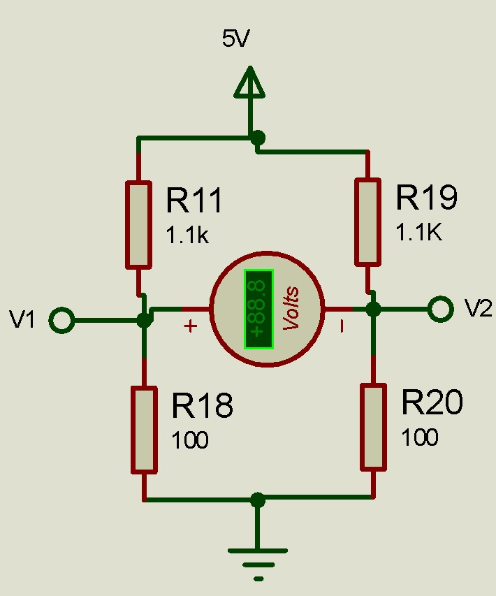
To take advantage of this phenomenon, one of the lower resistors is replaced by the PT100. When the temperature varies, the resistivity of the PT100 will also vary and therefore the voltage measured between V1 and V2 will vary, and this variation can be used to find the temperature value according to the table of values for the PT100.
Para aprovechar ese fenómeno se reemplaza una de las resistencias inferiores por la PT100, cuando la temperatura varíe lo hará también la resistividad de la PT100 y por lo tanto variará el voltaje medido entre V1 y V2 pudiéndose aprovechar esta variación para hallar el valor de la temperatura según la tabla de valores para la PT100
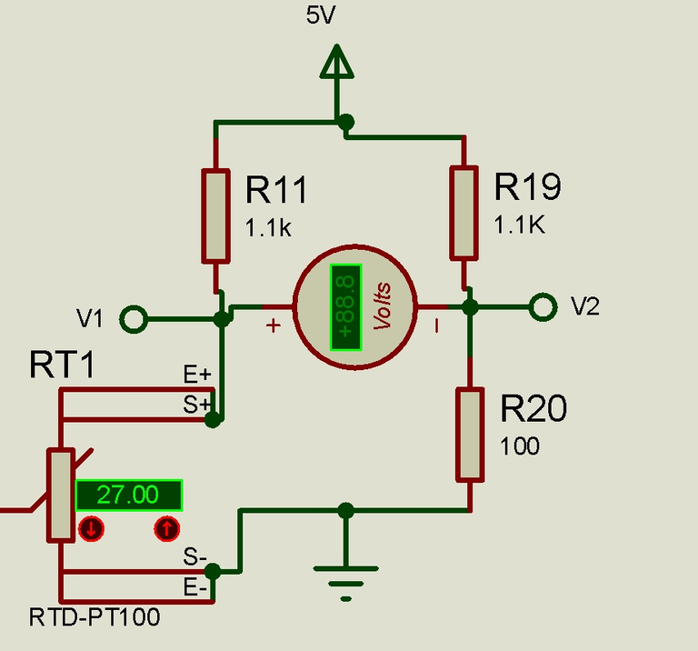
The value of the resistor R11 was chosen to be 1.1K to limit the current through the PT100 to less than 5mA, applying Ohm's Law this current through R11 and the PT100 is I=V/(R11+PT100).
Since the PT100 will have a minimum value of 100 ohms at 0 degrees we can assume that the total resistance will always be greater than 1.2K so I=5V/1.2K = 4.1mA, and that will be the maximum current, R19 and R20 are chosen with those values for convenience to form the bridge mirror.
Since the voltage at each divider of the bridge is of the order of mV and the measured result will be the subtraction of the two voltages, a differential mode operational amplifier is proposed to receive and amplify the resulting voltage.
The gain is chosen according to the design and is given by Rf/Ri +1.
El valor de la resistencia R11 se escogió de 1.1K para limitar la corriente que pasa por la PT100 a menos de 5mA, aplicando Ley de Ohm esta corriente que atraviesa R11 y la PT100 es I=V/(R11+PT100)
Como la PT100 tendrá un valor mínimo de 100 ohmios a 0 grados podemos asumir que la resistencia total siempre será mayor a 1.2K por lo tanto I=5V/1.2K = 4.1mA, y esa será la corriente máxima, R19 y R20 se escogen con esos valores por conveniencia para formar el espejo del puente.
Ya que el voltaje en cada divisor del puente es del orden de los mV y el resultado medido será la resta de los dos voltajes, se propone un amplificador operacional en modo diferencial para recibir y amplificar el voltaje resultante.
La ganancia se escoge según el diseño y viene dado por Rf/Ri +1.
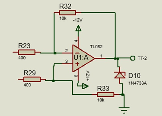
The D10 Zener diode is a 5.1V diode, it is used there to saturate the output of the amplifier to 5.1V in order to protect the input of the reader microcontroller which generally support up to 5V, the resistors shown allow a gain of 26 but can be adjusted to the needs of the process.
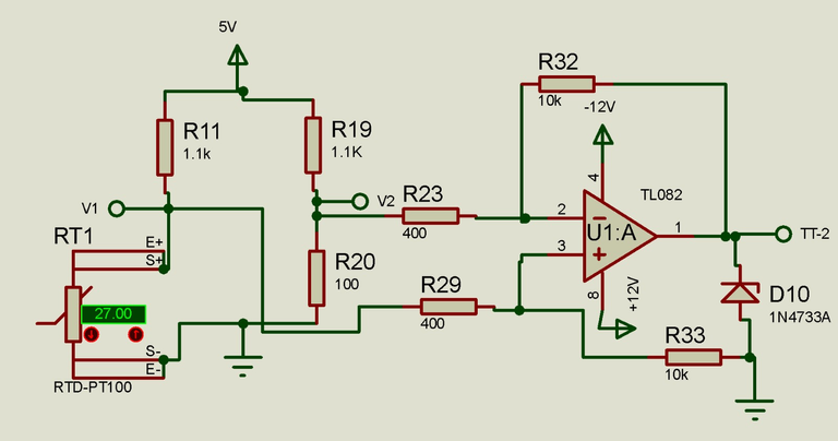
The bridge and amplifier will be coupled into a single circuit as shown below.
El diodo Zener D10 es un diodo de 5.1V, se usa ahí para saturar la salida del amplificador a 5.1V con el fin de proteger la entrada del microcontrolador lector que generalmente soportan hasta 5V, las resistencias mostradas permiten una ganancia de 26 pero se pueden ajustar a las necesidades del proceso.
El puente y el amplificador se acoplarán en un solo circuito como se muestra a continuación.
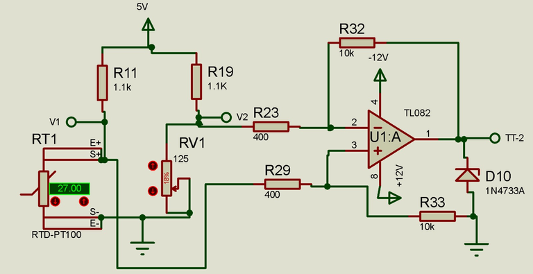
The resistor R20 can be replaced by a potentiometer in order to apply corrective adjustments if necessary, this potentiometer can be with a value of 0-125.
La resistencia R20 se puede reemplazar por un potenciómetro con la finalidad de aplicar ajustes correctivos en caso de ser necesario, este potenciómetro puede ser con un valor de 0-125.

If you want to give an extra boost to the blog with a donation you can send it to the addresses:
Si quieres darle un impulso extra al blog con una donación puedes enviarla a las direcciones:
BEP-20: 0x5Aee5e3e3ED3203e77eF0d8Bb3E3a420E5229Ce0
ERC-20: 0x5Aee5e3e3ED3203e77eF0d8Bb3E3a420E5229Ce0
Arbitrum One: 0x5Aee5e3e3ED3203e77eF0d8Bb3E3a420E5229Ce0
Polygon: 0x5Aee5e3e3ED3203e77eF0d8Bb3E3a420E5229Ce0
Avalanche: 0x5Aee5e3e3ED3203e77eF0d8Bb3E3a420E5229Ce0
Wow, what a thorough and insightful explanation of the circuit for data acquisition from a PT100 temperature sensor!
I'm really impressed by the depth of your knowledge and your ability to convey complex concepts in a clear and understandable way.
Your detailed breakdown of the PT100's functionality and the design considerations for the circuit really helped me grasp the topic better.
Plus the inclusion of diagrams and explanations of component choices was very helpful.
Thank you for sharing your expertise in this field!
♥️
Your comment fills me with great emotion, I'm really glad you found it useful, thank you for letting me know. Those are the details that motivate me to keep working to offer this kind of content.
Best wishes.
Always welcome friend ♥️
Thanks for your contribution to the STEMsocial community. Feel free to join us on discord to get to know the rest of us!
Please consider delegating to the @stemsocial account (85% of the curation rewards are returned).
Thanks for including @stemsocial as a beneficiary, which gives you stronger support.