Characteristics of electronic filters EN/ES
Now we know that an electronic filter is responsible for allowing or blocking the passage of a current according to the frequency that has been configured.
It is time to move on to the next step in which we will learn about the characteristics of electronic filters.
Ahora sabemos que un filtro electrónico se encarga de permitir o bloquear el paso de una corriente segun la frecuencia que se haya configurado.
Es hora de pasar a la siguiente etapa en la que conoceremos las características de los filtros electrónicos.
For illustrative purposes we will choose a range of frequencies between 1 and 900Hz and we will establish by mutual agreement that frequencies below 300Hz will be considered as low frequencies, frequencies between 300Hz and 600Hz will be medium frequencies and frequencies above 600Hz will be high frequencies.
We can then establish 3 frequency bands and we find here one of the first important characteristics, that is, the frequency bands or sets of frequencies to be attenuated and those not to be attenuated.
From this point we can design 4 types of filters:
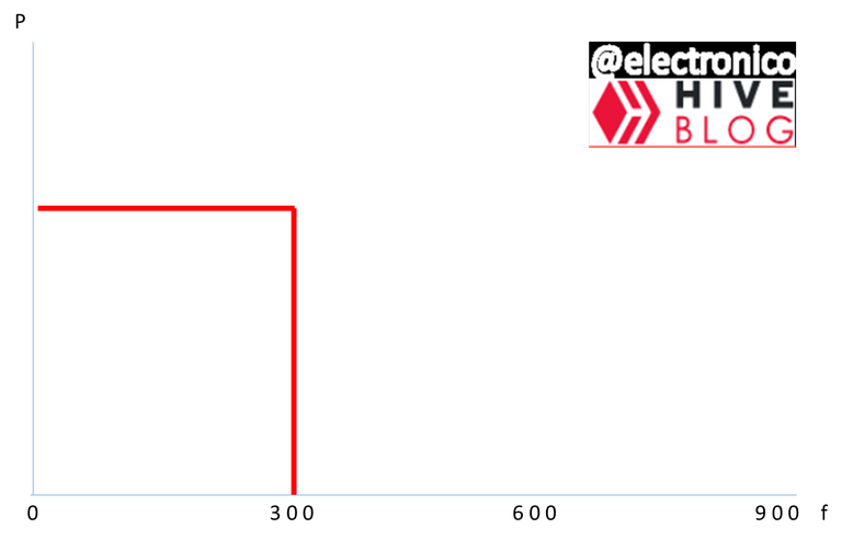
- Low pass filter: An ideal low pass filter will be the one that allows a 100% energy delivery in its output for frequencies lower than 300Hz (respecting our previous agreement) and completely attenuates all signals with frequencies higher than this value.
Para efectos ilustrativos vamos a escoger un rango de frecuencias entre 1 y 900Hz y estableceremos por acuerdo mutuo que las frecuencias por debajo de 300Hz serán consideradas como baja frecuencia, las frecuencias entre 300Hz y 600Hz serán frecuencias medias y las frecuencias mayores a 600Hz serán frecuencias altas.
Podemos entonces establecer 3 bandas de frecuencias y encontramos aquí una de las primeras características importantes, esto es, las bandas de frecuencias o conjuntos de frecuencias que se van a atenuar y las que no.
Partiendo de este punto podemos diseñar 4 tipos de filtros:
- Filtro pasa bajos: Un filtro pasa bajos ideal sera el que permita una entrega de energía en su salida del 100% para frecuencias inferiores a 300Hz (respetando nuestro acuerdo anterior) y atenúe por completo todas las señales con frecuencias mayores a este valor.
But in reality the ideal conditions are almost impossible to achieve, so it is also impossible with current technologies to achieve a filter that has a frequency response similar to that of the graph.
Pero en la realidad las condiciones ideales son casi imposibles de conseguir por lo cual también es imposible con las tecnologías actuales conseguir un filtro que tenga una respuesta en frecuencia similar a la de la gráfica.
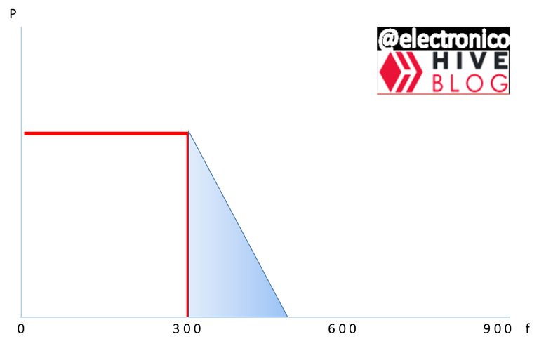
The new zone represents unwanted frequencies that will inevitably appear in the system, however these are attenuated as they move away from the maximum frequency that we chose as permissible (300Hz) so that frequency is called cutoff frequency because from it the signals with higher frequencies should be cut or attenuated by the effect of the filter.
We can also determine the quality factor of the filter, with this we determine how efficient it is and we can use the formula Q = fo/B, where fo is the resonance frequency and B is the bandwidth.
Depending on the number of reactive components that the filter has (capacitors and inductors) can be classified as n-order, where n is defined by the reactive components, if it has 1 it is first order and so on.
These characteristics are applicable to all the filters that we are going to describe.
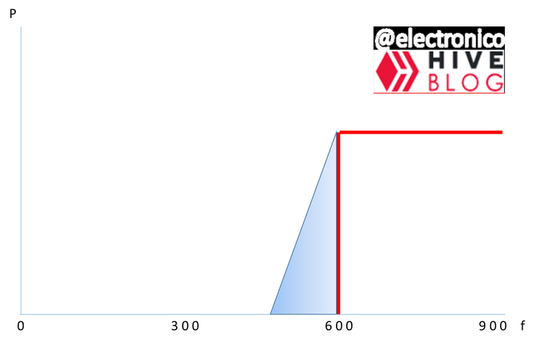
- High pass filter: This will block frequencies below 600Hz (value that we agreed as cut-off frequency at the beginning) and will allow the passage of higher frequencies.
La nueva zona representa frecuencias no deseadas que aparecerán inevitablemente en el sistema, sin embargo estas se atenúan a medida que se alejan de la frecuencia máxima que escogimos como permisible (300Hz) por lo cual esa frecuencia se denomina frecuencia de corte pues a partir de ella las señales con frecuencias mayores se deberian cortar o atenuar por el efecto del filtro.
También podemos determinar el factor de calidad del filtro, con esto se determina que tan eficiente es y se puede usar la formula Q = fo/B, donde fo es la frecuencia de resonancia y B el ancho de banda.
Según el número de componentes reactivos que tenga el filtro (Capacitores e inductores) se pueden clasificar de n orden, donde n es definido por los componentes reactivos, si tiene 1 es de primer orden y así sucesivamente.
Estas características son aplicables a todos los filtros que vamos a describir.
- Filtro pasa altas: Este bloqueara las frecuencias por debajo de 600Hz (valor que convenimos como frecuencia de corte al principio) y permitirá el paso de frecuencias mayores.
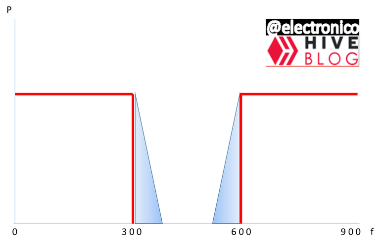
- Band pass filter: This type of filter allows output at a certain frequency range and attenuates frequencies above and below that range.
In our convention we chose the range between 300Hz and 600Hz.
- Filtro pasa banda: Este tipo de filtros permite la salida a un determinado rango de frecuencia y atenúa las frecuencias que estén por encima y por debajo de dichos rangos.
En nuestro convenio escogimos el rango entre 300Hz y 600Hz.

- Band suppressor: This will let all frequencies pass except a certain band, if we want a filter that suppresses the band that we let pass in the previous graph we would obtain a frequency response that can be represented as follows:
- Supresor de banda: Este dejara pasar todas las frecuencias excepto una banda determinada, si queremos un filtro que suprima la banda que dejamos pasar en el gráfico anterior abstendríamos una respuesta en frecuencia que se puede representar como sigue:
The output power is measured in decibels (dB) and is given by the ratio Vout/Vin (transfer function).
(dB) and is given by the Vout/Vin ratio (transfer function).
I believe that knowing these details we are ready to start digging into the electronic circuits but we will leave it for the next installment.
Thank you for joining me once again and I remain attentive to the comments section.
La potencia de salida se mide en decibelios
(dB) y viene dada por la relacion Vout/Vin (función de transferencia).
Considero que conociendo estos detalles estamos listos para comenzar a indagar en los circuitos electrónicos pero lo dejaremos para la siguiente entrega.
Te agradezco por acompañarme una vez mas y quedo atento a la sección de comentarios.

Thanks for your contribution to the STEMsocial community. Feel free to join us on discord to get to know the rest of us!
Please consider delegating to the @stemsocial account (85% of the curation rewards are returned).
Thanks for including @stemsocial as a beneficiary, which gives you stronger support.
Congratulations @electronico! You have completed the following achievement on the Hive blockchain And have been rewarded with New badge(s)
Your next target is to reach 40000 upvotes.
You can view your badges on your board and compare yourself to others in the Ranking
If you no longer want to receive notifications, reply to this comment with the word
STOPCheck out our last posts: