Basic Optical Communications System. EN/ES
We are more and more immersed in optical communications systems, after the fundamental theories and the description of some parameters and tools we can now create and analyze an optical communications system that will serve to familiarize us with the most basic components and analysis.
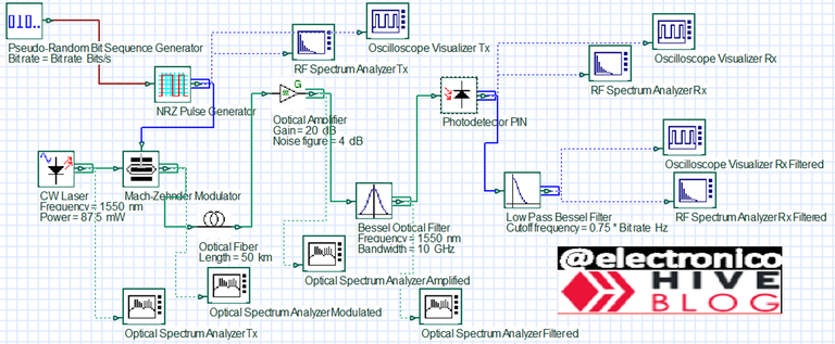
In this article we will use the OptiSystem software to create such a system but it will be done step by step and in a very detailed and illustrated way, defining the elements that make up the system, its function within the system and how they affect the signal.
That's the end of the theory, let's go to practice!
Cada vez estamos más sumergidos en los sistemas de comunicaciones ópticas, luego de las teorías fundamentales y la descripción de algunos parametros y herramientas ya podemos crear y analizar un sistema de comunicaciones óptico que servirá para familiarizarnos con los componentes y análisis más básicos.
En este artículo se usará el software OptiSystem para crear dicho sistema pero se hará paso a paso y de forma muy detallada e ilustrada, definiendo los elementos que componen el sistema, su función dentro del mismo y la forma como estos afectan la señal.
Es el fin de la teoría. ¡Vamos a la práctica!
We must remember that our source signal comes from an electronic system, this will be a digital pulse signal that will contain the information to be transmitted.
To generate this signal in the Optisystem software we will use a random bit generator, we will connect it to an NZR encoder and the output of this block will be the signal that we want to transmit (Tx).
Debemos recordar que nuestra señal de origen proviene de un sistema electrónico, esta sera una señal de pulsos digitales que contendra la informacion que se desea transmitir.
Para generar esta señal en el software Optisystem usaremos un generador de bits aleatorios, este lo vamos a conectar con un codificador NZR y la salida de este bloque sera la señal que deseamos transmitir. (Tx)
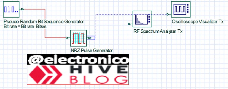
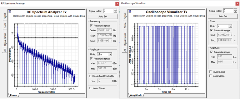
A frequency spectrum analyzer and an oscilloscope are used to capture the shape and data of the generated signal, it is important to note that at this point the signal is still electronic (so we can see it on the oscilloscope) and that throughout the process we will see two types of spectrum analyzers, one RF when the signal is in electrical format and another optical. Depending on the shape of the signal, one or the other will be used for its analysis.
The signal at this point we call it Tx because it is the signal to be transmitted, if we observe it in the oscilloscope and the spectrum analyzer will have the following form.
Se usan un analizador de espectro de frecuencias y un osciloscopio para captar la forma y datos de la señal generada, es importante resaltar que en este punto la señal aún es electronica (por eso podemos verla en el osciloscopio) y que en todo el proceso veremos dos analizadores tipos de analizadores de espectro, uno RF cuando la señal está en formato eléctrico y otro óptico. Según la forma de la señal se usará uno u otro para su análisis.
La señal en este punto la llamamos Tx porque es la señal que se desea transmitir, si la observamos en el osciloscopio y el analizador de espectro tendrá la siguiente forma.
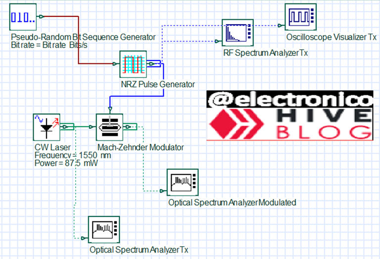
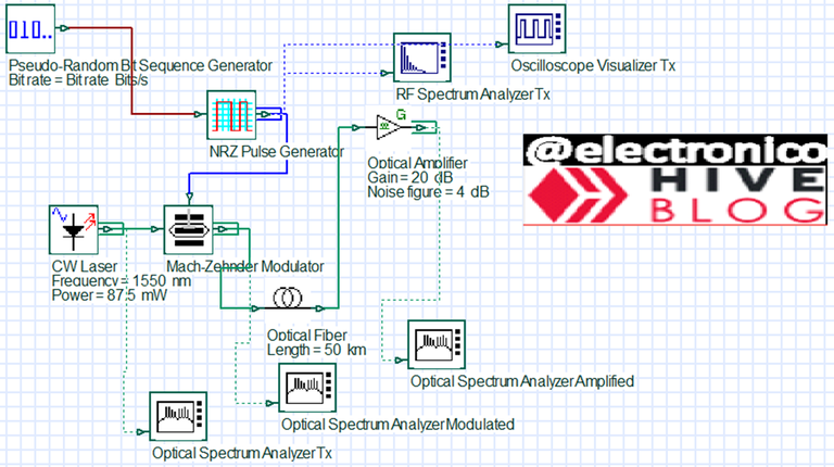
We need an optical source that will be in charge of generating the carrier signal, for this purpose we choose a laser that we can identify in Optisystem as CW Laser.
When we use a component in OptiSystem and we want to modify its parameters just double click on it and it will open a configuration window for the component, in this case we will use a wavelength of 1550nm. It is important to note that this value is another way to represent the frequency, also the transmit power is configured, in this case it will be 85.7mW.
Se necesita una fuente óptica que sera la encargada de generar la señal portadora, para este propósito se escoge un láser que podemos identificar en Optisystem como CW Laser.
Cuando usamos un componente en OptiSystem y queremos modificar sus parametros solo basta con hacer doble click en el mismo y se abrirá una ventana de configuración para el componente, en este caso usaremos una longitud de onda de 1550nm. Es importante señalar que este valor es otra forma de representar la frecuencia, también se configura la potencia de transmisión, en este caso serán 85.7mW.

Using an optical spectrum analyzer we observe the power of the signal at different wavelengths and we see that the highest power is indeed obtained at 1550nm as it should be.
Mediante un analizador de espectro óptico observamos la potencia de la señal a diferentes longitudes de onda y vemos que efectivamente se obtiene la mayor potencia a 1550nm como debe ser.

A Mach-Zehnder Modulator is a device that is responsible for modulating the optical signal with the electronic signal, for this we place the block and connect the two signals to it.
Un Mach-Zehnder Modulator es un dispositivo que se encarga de modular la señal óptica con la señal electrónica, para ello colocamos el bloque y conectamos las dos señales al mismo.
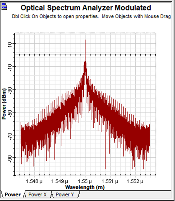
Now our signal is purely optical, this implies that we cannot look at it in an oscilloscope, we can only use an optical spectrum analyzer to verify that the power is in the proper wavelength, in addition to verify the signals (noise) that may appear at each stage of transmission.
The modulated signal seen from an optical spectrum analyzer will have the following form.
Ahora nuestra señal es puramente óptica, esto implica que no podemos mirarla en un osciloscopio, solo podemos usar un analizador de espectros óptico para verificar que la potencia se encuentra en la longitud de onda adecuada, además de verificar las señales (ruido) que pudiesen aparecer en cada etapa de la transmisión.
La señal modulada vista de desde un analizador de espectros óptico tendrá la siguiente forma.
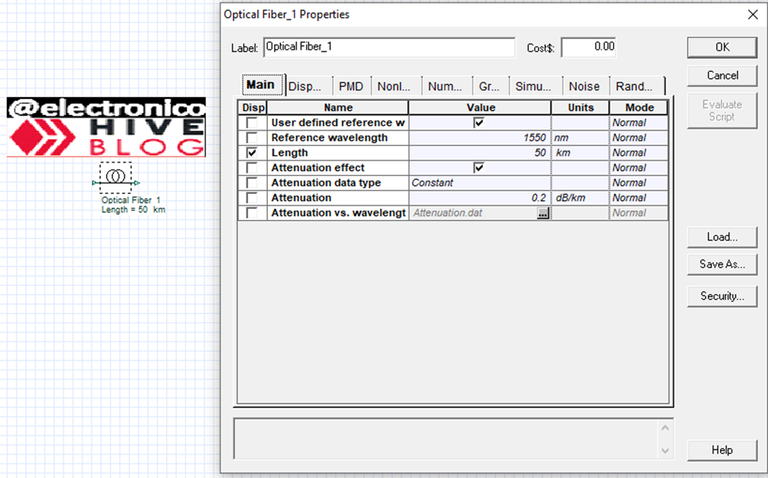
Now that our signal is ready to be transmitted we must make the laying of the optical fiber, it will only be 50Km of fiber but do not worry, it can be done in OptiSystem just by dragging a component 😉.
Once the fiber is placed in the work area we can double click to configure the parameters of the fiber, change length, attenuation and all the values concerned, for the case at hand there will be no changes in the default component.
Ahora que nuestra señal ésta lista para ser transmitida debemos hacer el tendido de la fibra óptica, solo serán 50Km de fibra pero no te preocupes, se puede hacer en OptiSystem solo con arrastrar un componente. 😉
Una vez colocada la fibra en el área de trabajo podemos dar doble click para configurar los parametros de la misma, cambiar longitud, atenuación y todos los valores concernientes, para el caso que nos ocupa no habrán cambios en el componente por defecto.
After our signal has traveled 50Km it arrives at its destination with losses due to the attenuation of the fiber, the first treatment that we must give it is to pass it through an amplifier so that the recovery of the same one is more effective.
Here we will use an optical amplifier with a gain of 20 dB, although it is physically different from an electronic one, the function is the same, to amplify the signal.
Luego de nuestra señal haber recorrido 50Km llega a su destino con pérdidas debido a la atenuación de la fibra, el primer tratamiento que debemos darle es el de pasarla por un amplificador para que la recuperación de la misma sea más efectiva.
Aquí usaremos un amplificador óptico con una ganancia de 20 dB, aunque es físicamente distinto a uno electrónico la función es la misma, amplificar la señal.
We want to see how our signal has been affected during the trip after having been amplified, so we use the optical spectrum analyzer again. We will be able to notice our signal and with it any noise in the different wavelengths (green color in the graph).
Queremos ver como ha sido afectada nuestra señal durante el viaje luego de haber sido amplificada, para ello usamos nuevamente el analizador de espectros óptico. Podremos notar nuestra señal y con ella cualquier ruido en las diferentes longitudes de onda (color verde en la gráfica).

Our signal is still present, but it is accompanied by noise throughout the spectrum, we have already learned in our articles about filters that are very useful to eliminate noise, at this point it is time to clean our signal.
We will use a Bessel type optical filter which of course we must set to the frequency of our signal of 1550nm and the bandwidth we will leave it at 10Ghz.
Nuestra señal sigue presente, pero está acompañada de ruido en todo el espectro, ya aprendimos en nuestros artículos sobre filtros que son muy útiles para eliminar ruido, en este punto es hora de limpiar nuestra señal.
Usaremos un filtro óptico tipo Bessel el cual por supuesto debemos configurar a la frecuencia de nuestra señal de 1550nm y el ancho de banda lo dejaremos en 10Ghz.

After filtering the signal it is ready to be taken to the receiver which will convert it back into an electrical signal, but first we need to look at the shape of the signal in the optical spectrum analyzer in order to see how the filtering has affected the signal and understand why this stage is always of great importance.
Luego de filtrar la señal está lista para llevarla al receptor que se encargará de volverla a convertir en una señal eléctrica, pero antes necesitamos mirar la forma de la señal en el analizador de espectros óptico con la finalidad de ver como el filtrado ha afectado la señal y comprender por qué esta etapa siempre es de gran importancia.

At this point we can say that the optical system has already fulfilled its function, which was to transport the signal between two points separated by a great distance at a high speed and with a bandwidth that could not have been achieved with copper wires.
Now a photodetector PIN will be in charge of receiving the light pulses and converting them into electrical pulses.
En este punto podemos decir que el sistema óptico ya ha cumplido su función que fue transportar la señal entre dos puntos separados por una gran distancia a gran velocidad y con un ancho de banda que no se hubiera podido alcanzar con hilos de cobre.
Ahora un PIN fotodetector se encargará de recibir los pulsos de luz y convertirlos en pulsos eléctricos.
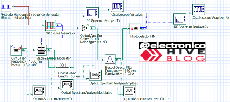
Now that our signal again has electrical characteristics we can and want to analyze it with an oscilloscope and an RF spectrum analyzer to verify that we have received something similar to what we asked for.
What we received is shown in the following image.
Ahora que nuestra señal de nuevo tiene características eléctricas podemos y queremos analizarla con un osciloscopio y un analizador de espectros RF para comprobar que nos ha llegado algo parecido a lo que pedimos.
Lo recibido se manifiesta en la siguiente imagen.

Wow, it looks a bit spoiled from the trip 😂, we can still do something more for it to recover it a bit more. We'll use a Bessel low pass filter but now not optical but electronic (because that's the way we have the signal now) and God willing!!!!
Vaya, parece un poco estropeada del viaje 😂, aún podemos hacer algo más por ella para recuperarla un poco más. Usaremos un filtro pasa bajos de Bessel pero ahora no óptico sino electronico (porque es la forma en que tenemos ahora la señal) y que sea lo que Dios quiera!!!

Are you ready to see the final product?
At this point our signal is ready to be delivered, it is the end of our design so the signal obtained will be the final one, again we are going to see the oscilloscope and the RF spectrum analyzer to evaluate how much the signal has improved after filtering.
¿Estás listo para ver el producto final?
En este punto ya nuestra señal está lista para ser entregada, es el fin de nuestro diseño así que la señal obtenida sera la definitiva, de nuevo vamos a ver el osciloscopio y el analizador de espectros RF para evaluar cuánto ha mejorado la señal luego del filtrado.

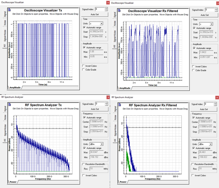
I would say that it is not so bad for our first time in the blog 😊, also we must take into account that we are designing the system as basic as possible because the main objective is that the reader can understand each stage of the system as clear and simple as possible.
Finally we will see an image in which using the oscilloscope and the RF spectrum analyzer we can compare the transmitted image with the received one.
Yo diría que no está tan mal para ser nuestra primera vez en el blog 😊, además debemos tomar en cuenta que estamos diseñando el sistema lo más básico posible porque el objetivo principal es que el lector pueda comprender cada etapa del sistema lo más claro y simple posible.
Finalmente veremos una imagen en la que mediante el osciloscopio y el analizador de espectros RF podemos comparar la imagen transmitida con la recibida.
I would not like to say goodbye without first thanking you for having accompanied my signal and me in these 50Km of electro-optical learning. Seriously, thank you for your continuous support 😉.
No quisiera despedirme sin antes agradecerte por habernos acompañado a mi señal y a mi en estos 50Km de aprendizaje electro-óptico. En serio, gracias por el apoyo continuo! 😉

Thanks for your contribution to the STEMsocial community. Feel free to join us on discord to get to know the rest of us!
Please consider delegating to the @stemsocial account (85% of the curation rewards are returned).
Thanks for including @stemsocial as a beneficiary, which gives you stronger support.
Thank you!! ❤