SEE WHAT HAPPENS TO YOUR PC IF YOU GET THIS MESSAGE.. [ES-EN]
ESPAÑOL
Hola , saludos a toda la comunidad, es un placer estar por primera vez por acá compartiendo mis experiencias, pues como amante de las tecnologías me siento identificado con esta comunidad, y con su visto bueno vengo a hacer un poco de vida entre ustedes.
Recientemente se me acercó un amigo pidiéndome ayuda para resolver un problema que estaba presentando su Computadora Personal (PC) la cual al encenderla solo llegaba hasta un punto dónde mostraba un cartel informándole acerca de un error que estaba presentando la Motherboard, y debido a esto no podía culminar el proceso de encendido , inhabilitando por completo la PC.
Antes de pasar a las especificidades quiero comentarles que estube buscando entre las comunidades con las que me identifico dónde subir esta publicación , pues quería llegar con esta experiencia a la mayor cantidad de personas con acceso a una PC y que por ende se les pudiera en algún momento presentar este tipo de problema del que les hablaré más adelante. Fue grata la sorpresa al leer las normas de la comunidad y saber que acá se permiten este tipo de publicaciones, además de que por lógica es más probable de que concurran acá personas con una PC y mi contenido les sirva de algo.
Entrando en materia...
La Motherboard de mi amigo es una Asus P8H77-V LE Rev.2.0 con un socket LGA1155 y un micro Intel Core i5-3330 este es un micro de tercera generación lanzado en el tercer trimestre del año 2012.
El problema que mostraba la placa era el típico error de USB Device Over Current Satatus Detected System Will Shut Down After 15 Seconds. Esta notificación se muestra cuando uno de los puertos USB de la placa está en cortocircuito, o uno de los dispsitivos conectados presenta un sobreconsumo de corriente. Sin embargo en ocasiones la causa no se debe a los puertos o los dispositivos conectados a ellos, sino a los componentes electrónicos asociados a los puertos USB, o a una mala interpretación de la señal que activa el estado de sobrecorriente (OC por sus siglas en inglés) la cual se encuentra fuera de parámetros debido a la desvalorización o problemas en los componentes electrónicos asociados al circuito que se encarga de dar una muestra de los 5 volt del USB, para que sea interpretada por el Concentrador de Controladores de Plataforma (PCH) o chipset cómo se le conoce también. En el siguiente link les dejaré una definición de que es el PCH y su función en las placas bases según el sitio hardzone.es.
En las siguientes imágenes les muestro la placa base y como se manifiesta el problema en este tipo de placas.
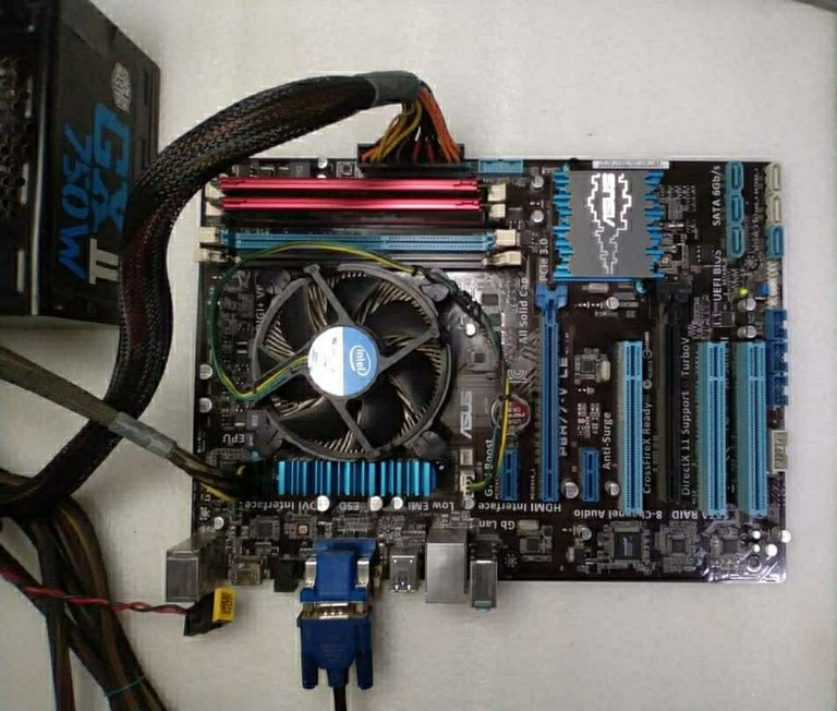
Placa Asus P8H77-V LE Rev2.0
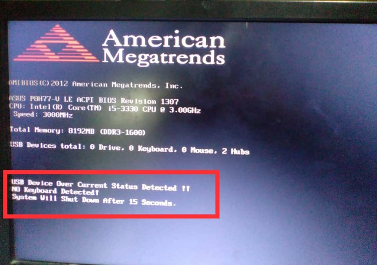
Notificación donde alerta acerca de un sobreconsumo en un dispositivo USB, y adelanta que el sistema se apagará después de 15 segundos
Este tipo de problema en algunas placas pude manifestarse de la forma que le mostré en la imagen anterior, evitando que el sistema culmine su proceso de encendido y por ende nos deja una PC inservible hasta tanto no se solucione el problema, en otro tipos de placas la PC inicia y te permite trabajar en ella sin problemas pero con la diferencia de que se deshabilita el puerto USB asociado con el problema, o el supuesto sobreconsumo.
A continuación te diré cómo resolví el problema y que puedes hacer tú si le pasara lo mismo a tu PC.
Cuando vemos en la pantalla el mensaje USB Device Over Current Satatus Detected System Will Shut Down After 15 Seconds debemos seguir la siguiente metodología.
1- Primeramente desconectamos todos los periféricos de la placa que hagan uso de los puertos USB ( Teclado, mouse, bocinas, memorias USB, panel frontal del USB, ect. ) nos aseguramos de que no quede nada conectado a los puertos USB de la placa, además desconectamos también todos los discos duros de almacenamiento interno, este último paso es importante ya que será necesario encender y apagar la PC varias veces y de esta forma evitamos causarle algún daño a los discos duros. Una vez que se cumplan las condiciones anteriores se procede a encender la PC, si desaparece el mensaje y continúa su lógica de encendido, esto quiere decir que el problema lo presenta uno de los periféricos y ya solo quedaría identificar cuál de ellos es el causante. Para identificar el periférico con problemas basta con encender la PC con un periférico a la vez hasta que aparezca nuevamente el mensaje USB Device Over Current Satatus Detected System Will Shut Down After 15 Seconds y lo habremos identificado en ese punto.
2-Si con los pasos anteriores no se resuelve el problema, continuamos con la metodología y lo siguiente sería medir los 5 volt en todos los puertos USB de la placa, para esto se necesitaría un multímetro.
Antes de continuar aclaro que existen placas en las que los 5 volt del USB están prestes aún con la misma en Standby o sea se pueden medir sin necesidad de prender la PC, basta con tener la fuente de alimentación conectada a la toma de alimentación, pero existen otros tipos de placas en las que es necesario encender la PC para obtener los 5 volts en los puertos USB.
En el caso de la placa base de mi amigo fue necesario encenderla para poder medir los 5 volt.
Cuando realice las mediciones del voltaje en todos los puertos USB de la placa, todos presentaban los 5 volts sin problemas, lo que quiere decir que los USB y sus componentes asociados están funcionando correctamente. Este proceso no lo pude documentar fotográficamente pero les dejaré a continuación una imagen donde doy una idea de cómo y dónde medir el voltaje de los USB.
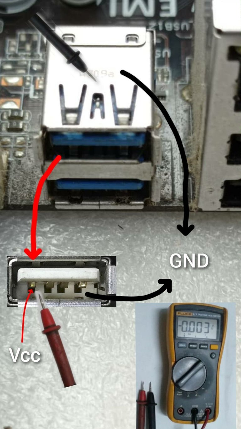
Con el multímetro en escala de voltaje de directa ponemos la punta negra en el cuerpo metálico del conector USB, y la punta roja en el pin 1 del conector USB como se muestra en la imagen.
Luego de haber medido todos los conectores USB y darme cuenta de que todos tenían los 5 volt correctamente, entonces pasé al siguiente paso de la metodología.
Una vez que llegué a este punto, empecé a sospechar que el problema se debía a la señal que es interpretada por el PCH para determinar si el consumo de los puertos USB está en parámetros o existe un consumo excesivo de corriente.
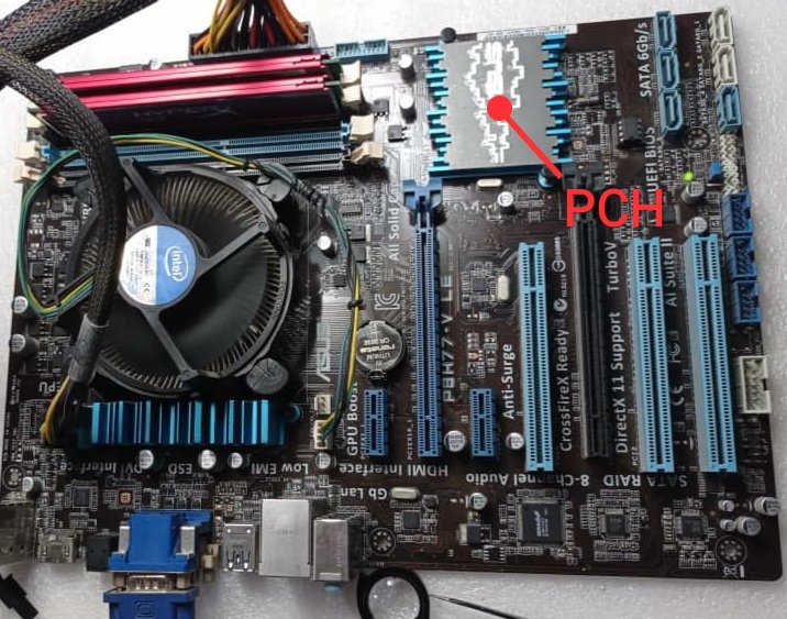
Acá señalo donde se encuentra el PCH o Chipset, el cual está debajo del disipador de calor que se observa en la imagen
El PCH toma una muestra de los 5 volt de los puertos USB, a través de un divisor de voltaje formado por dos resistencia, en algunos tipos de placas la señal es enviada al PCH a través de un circuito integrado de 6 pines , pero en la placa de mi amigo la muestra es tomada de un divisor de voltaje formado por dos resistencias, cómo les represento en la siguiente ilustración.
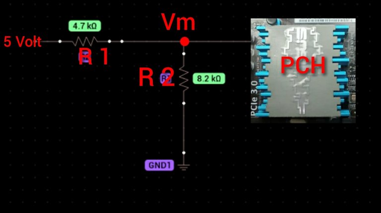
Aca se observa que por la izquierda de la resistencia R1 están los 5 volt del USB , esta resistencia forma un divisor de voltaje junto a R2 la cual está conectada además a tierra (GND) y en el punto Vm el PCH toma una muestra de los 5 volt del USB, esta muestra es el voltaje que se cae en R2.
En estos casos en el que el problema de la placa es debido a una mala interpretación de la señal o muestra que toma el PCH, se debe a qué una de esas resistencias (R1 o R2 ) se encuentran en mal estado y por tanto la solución radica en encontrar esa resistencias y medir la muestra de voltaje que le está llegando al PCH, para determinar si está en parámetros o no.
O sea la cosa consiste en encontrar esas resistencias en la placa , medir la muestra o señal que toma el PCH, y determinar cuál de las dos resistencias está en mal estado.
Para esto se debe conocer lo siguiente:
La señal o muestra que llega al PCH, normalmente debe de estar en el orden de los 3.3 volt, y se mide con un multímetro en el punto Vm, si está muy por debajo de los 3 volt pudiera existir una mala interpretación por parte del PCH.
Para llegar a este punto les diré que hice y que pueden hacer ustedes si fuera necesario.
Siguiendo con la metodología el siguiente paso sería identificar las resistencias del divisor de voltaje, y para localizarlas en la placa utilicé la aplicación para ordenador BoardViewer, en la cual se pude visualizar el esquema eléctrico del la placa base siempre y cuando puedas descargar el plano desde internet, además para hacer uso de este programa se necesita de una PC o Laptop, esto es indispensable.
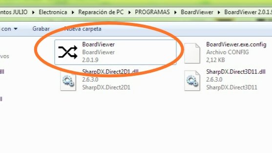
Está aplicación es un ejecutable por lo que no lleva instalación para abrirla
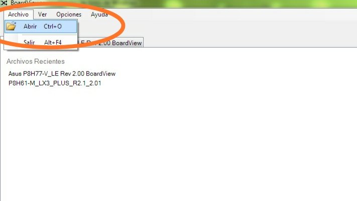
Pinchar en archivo y luego en abrir
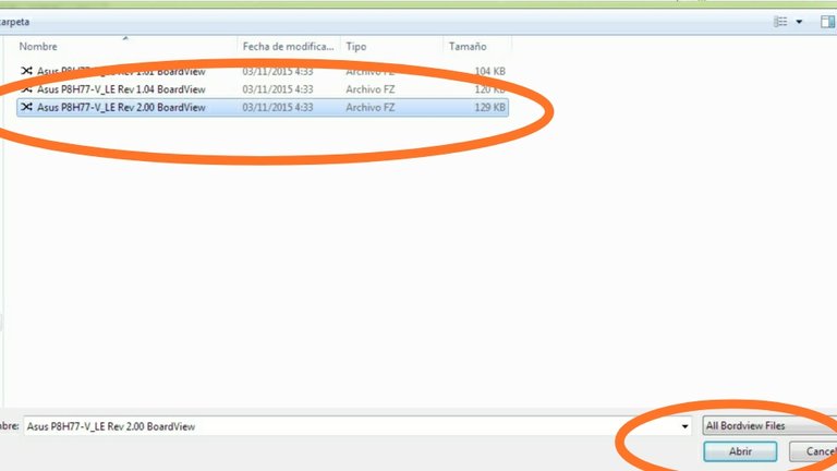
Seleccionar el esquema de la placa base previamente descargado desde internet y en el formato que soporta el programa, luego pinchar en abrir
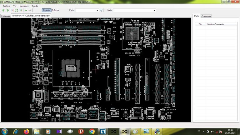
Al abrir el esquema, se muestra de esta forma, dónde se observa una representación exacta de la posición de los componentes en la placa base, así como todas sus estructuras y conectores
Debido a que el Boardview nos muestra una réplica exacta de la estructura física de la placa y la posición de los componentes en ella , solo basta con localizar cada componente en el esquema y buscarlo en la placa.
Para agilizar el trabajo, en este caso, busqué en la pestaña de búsqueda del BoardViewer, la señal que toma el PCH. Esta señal tiene diferentes nombres en los esquemas eléctricos según sea el tipo de placa y su fabricante.
Por ejemplo en el caso de las placas de MSI esta señal es nombrada como :
OC#0, OC#1, OC#2, USB_OCP#1,USB_OCP#2, etc.
El fabricante ASROCK utiliza en algunas placas los siguientes nombres: USB2_OC3#, OC#0123, OC#4567
GIGABYTE emplea N_USBOC_F, N_USBOC_7, N_USBOC_R
ASUS emplea * S_USB_OC*.
SI observan bien se darán cuenta que los nombres no son iguales para todas las placas pero tienen algo en común en todos los casos y es que todas llevan las siglas OC( Over Current ), por lo que a la hora de hacer la búsqueda solo hay que escribir las siglas OC en la pestaña de búsqueda del BoardViewer y les saldrán las señales que corresponden a los diferentes USB que presenta la placa.
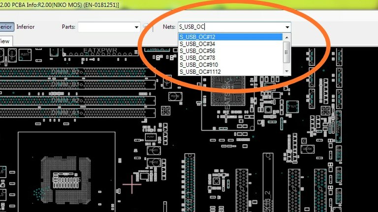
Cómo la placa de las que les hablo es Asus debo buscar en el BoardViewer las señales S_USB_OC, en la pestaña que les señalo. Se observa que automáticamente salen todas las señales de este tipo, que en esta placa son 7 señales, pues queda otra que no se observa en la imagen.
Luego de localizar las señales se selecciona la primera y automáticamente te muestra en el esquema los componentes donde se debe medir dicha señal
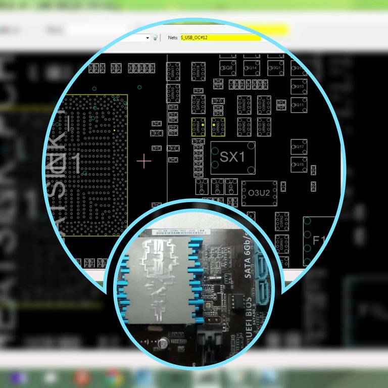
Acá se muestran en el esquema, señalados en amarillo los componentes y los pines donde se debe medir la señal S_USB_OC#12. Más abajo muestro el área física de la placa donde se encuentran esos componentes
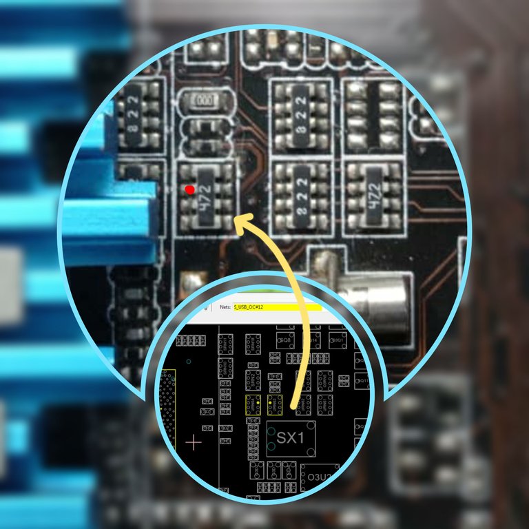
Esta es una mejor vista de los componentes y el punto donde se debe medir, en este caso lo señalé en rojo en la imagen de la placa, y esas son las resistencias que forman el divisor de voltaje, se debe medir con la punta roja del multímetro en el punto señalado en rojo.
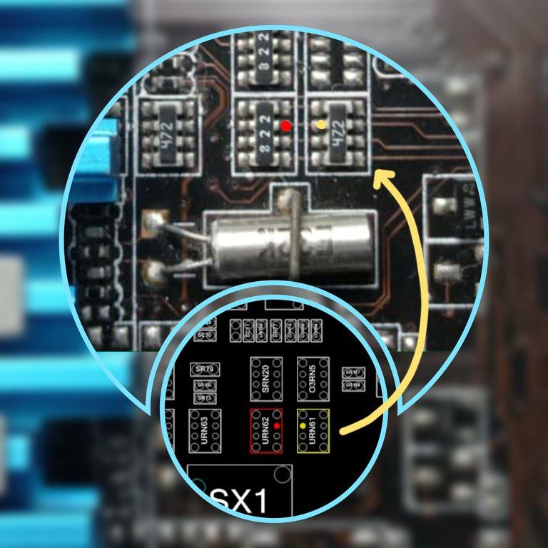
Acá se observan que al seleccionar la segunda señal (S_USB_OC#56) se seleccionan dos componentes diferentes, que son las resistencias que forman el divisor de voltaje, se trata de 4 resistencias de 8.2k en el primer componente, dispuestas en líneas horizontal y 4 resistencias de 4.7k en el segundo componente
De esta forma fui seleccionando todas las señales y las primeras 6 señales se deben medir en los puntos que les muestro a continuación.
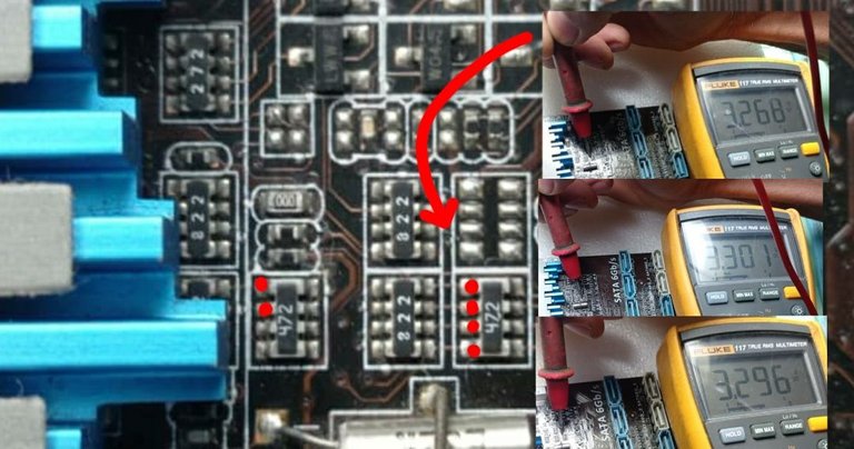
Los puntos rojos representan los pines donde se deben medir las señales que están asociadas con los puertos USB, y que serán interpretadas por el PCH.
En la aparte derecha del collage se observan algunas mediciones con el multímetro, y en todos los casos el voltaje estubo en el orden de los 3.3 volt, por lo que las 6 señales están en parámetros lo que quiere decir que estas no son las causantes del problema
Aún queda medir la 7ma señal que se nombra como S_USB_OC#34.
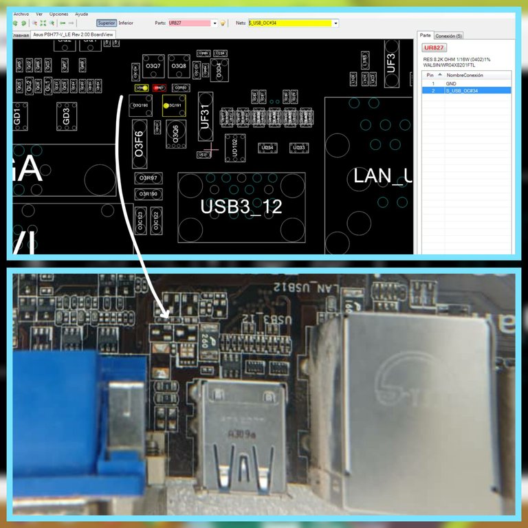
Al seleccionar la señal S_USB_OC#34, en el esquema se destacan en color amarillo y rojo las resistencias del divisor de voltaje , los puntos amarillos y rojo son comunes y en cualquiera de ellos se puede medir la señal
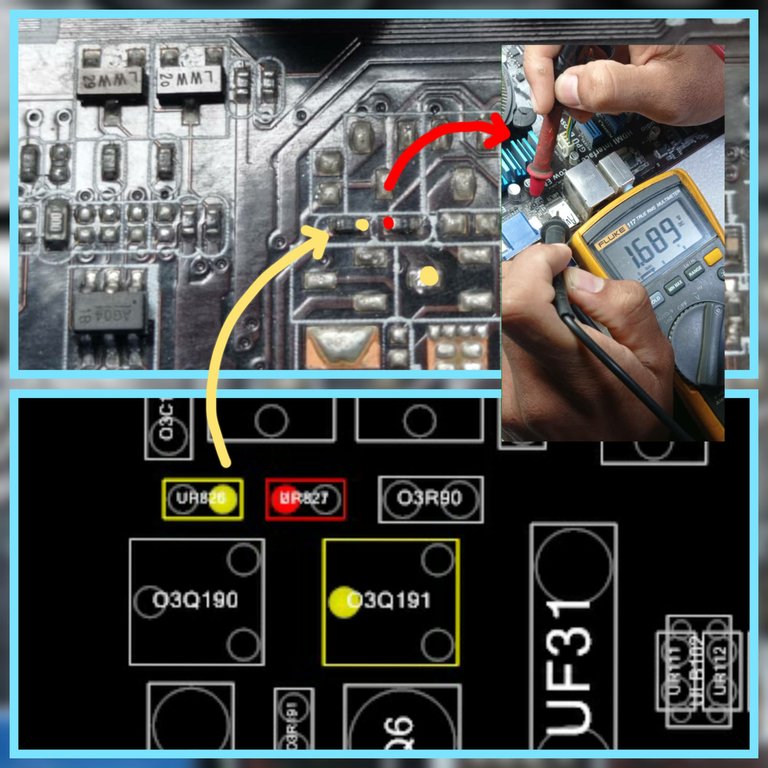
Acá se observa que la medición arrojó un valor de 1.68 volt lo significa que esta es la señal fuera de parámetros que provoca el problema.
Esta señal que está en 1.68 volt se debe a qué una de las resistencias o las dos que forman el divisor de voltaje se encuentran desvalorizadas, por lo que hay que retirarla y sustituirla.
Aquí estoy retirando la resistencia con ayuda de un cautín y una pinza, esta sería R2 en el diagrama del divisor de voltaje que les mostré anteriormente
Al retirarla y medirla con el multímetro me di cuenta que estaba desvalorizada, de un valor de 8.2k que debería tener solo tenía aproximadamente 2.3k, lo que provocaba que el voltaje que se caí en ella fuera de 1.68 volt, provocando este pequeño componente que la PC quedara inutilizable.
Luego de retirar la resistencia defectuosa, encendí la PC y automáticamente desapareció el problema e iniciaba correctamente la secuencia de encendido, por lo que con solo retirar la resistencia es suficiente para resolver el problema, sin embargo yo contaba con una de repuesto que extraje de una placa de un celular viejo.
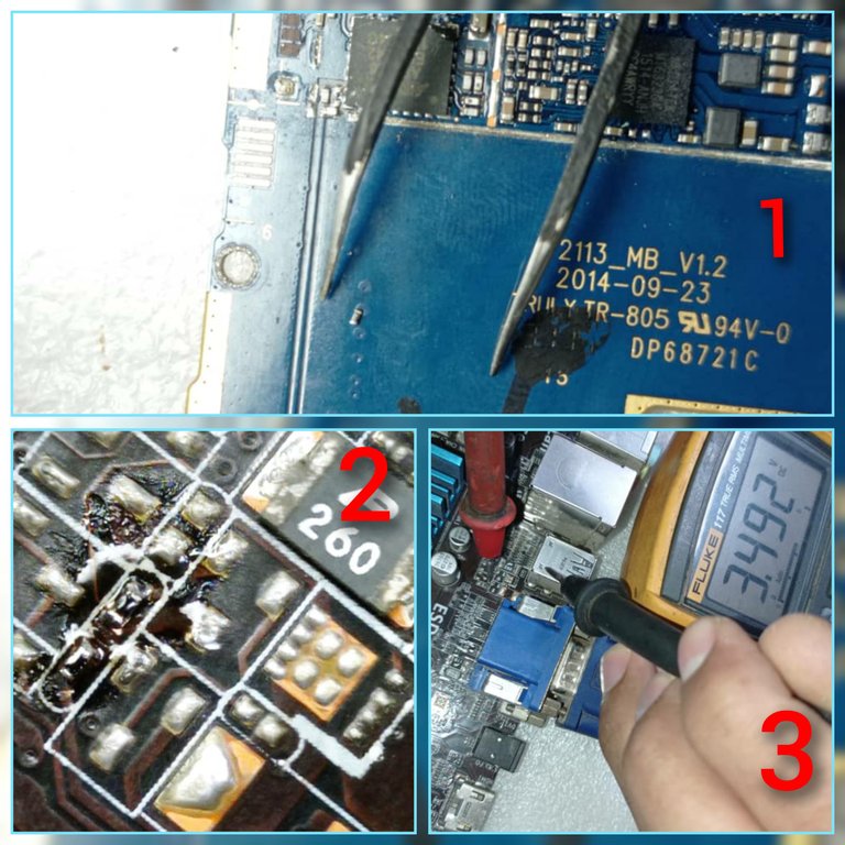
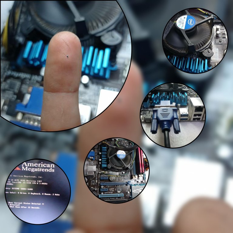
En la primera imagen del collage se muestra la resistencia de repuesto extraída de una placa de celular.
En la segunda imagen se muestra la resistencia soldada en la placa.
En la tercera imagen se muestra la medición de la señal después de la sustitución, la cual está en 3.4 volt y por ende en parámetros correctos, lo que permite que la PC inicie correctamente y sin problemas el encendido
Luego de sustituir la resistencia prendí la PC y este fue el resultado 👇👇
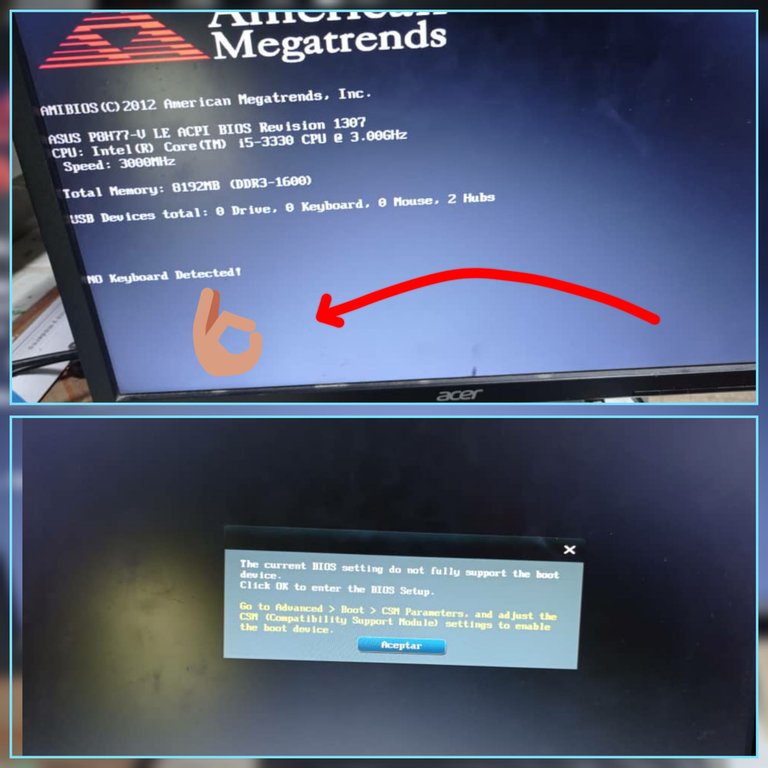
El mensaje desapareció, y se solucionó el problema, ya en la segunda foto del Collage se observa que pone un mensaje relacionado con el dispositivo booteable, esto quiere decir que necesita que se le conecte el disco duro para concluir con el encendido
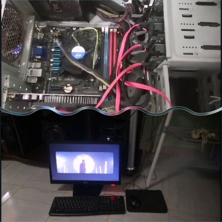
PC funcionando 👌🏼, y con mi amigo feliz y agradecido
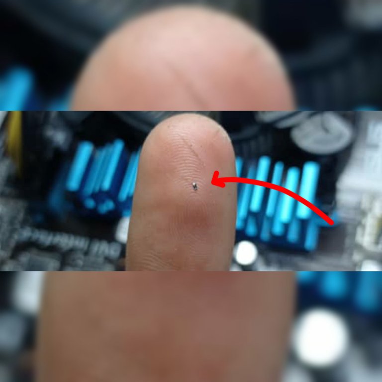
De esta forma solucioné esta falla, que fue causado por por una minúscula resistencia pero que provocó un gran problema.
Espero que esta experiencia les sirva por lo menos para conocimiento por si te sucede lo mismo, por supuesto, espero que nunca necesites reparar tu PC, para eso dale los mantenimientos que lleva 😉.
Un saludo para ti que me lees, y hasta el próximo post 😉.
Las imágenes son de mi autoría y fueron tomadas con un celular Xiaomi Redmi Note 9.
Imágenes editadas en la aplicación "Galería" del teléfono y la aplicación Foto Collage-GridArt.
Puedes verme en Facebook
ENGLISH
Hello, greetings to the whole community, it is a pleasure to be here for the first time sharing my experiences, because as a technology lover I feel identified with this community, and with your approval I come to make a little life among you.
Recently a friend approached me asking for help to solve a problem that was presenting his Personal Computer (PC) which when turning it on only reached a point where it showed a sign informing him about an error that was presenting the Motherboard, and because of this could not complete the process of ignition, completely disabling the PC.
Before going to the specifics I want to tell you that I was looking among the communities with which I identify myself where to upload this publication, because I wanted to reach with this experience to the largest number of people with access to a PC and therefore they could at some point present this type of problem that I will talk about later. It was a pleasant surprise to read the community rules and to know that this type of publications are allowed here, besides that by logic it is more likely that people with a PC will come here and my content will be useful to them.
Getting into the subject...
My friend's motherboard is an Asus P8H77-V LE Rev.2.0 with a LGA1155 socket and an Intel Core i5-3330 micro Intel Core i5-3330 this is a third generation micro released in Q3 2012.
The problem displayed by the board was the typical USB Device Over Current Satatus Detected System Will Shut Down After 15 Seconds error. This notification is displayed when one of the USB ports on the board is shorted, or one of the connected devices is over current. However sometimes the cause is not due to the ports or the devices connected to them, but to the electronic components associated to the USB ports, or to a misinterpretation of the signal that activates the overcurrent status (OC) which is out of parameters due to the devaluation or problems in the electronic components associated to the circuit that is responsible for giving a sample of the 5 volts of the USB, to be interpreted by the Platform Controller Hub (PCH) or chipset as it is also known. In the following link I will leave a definition of what is the PCH and its function in the motherboards according to the site hardzone.es.
In the following images I show you the motherboard and how the problem manifests itself in this type of boards.
Asus P8H77-V LE Rev2.0 board*
Notification alerting about an over-consumption on a USB device, and warning that the system will shut down after 15 seconds
This type of problem in some boards can manifest itself in the way I showed you in the previous image, preventing the system from completing its startup process and therefore leaving us with an unusable PC until the problem is solved, in other types of boards the PC starts and allows you to work on it without problems but with the difference that the USB port associated with the problem, or the alleged over-consumption, is disabled.
Here's how I solved the problem and what you can do if the same thing happens to your PC.
When we see on the screen the message USB Device Over Current Satatus Detected System Will Shut Down After 15 Seconds we must follow the following methodology.
1- First we disconnect all the peripherals of the board that make use of the USB ports (Keyboard, mouse, speakers, USB memories, front panel of the USB, ect.) we make sure that nothing is connected to the USB ports of the board, in addition we also disconnect all the hard disks of internal storage, this last step is important since it will be necessary to turn on and off the PC several times and in this way we avoid causing some damage to the hard disks. Once the previous conditions are fulfilled, the PC is turned on, if the message disappears and continues its logic of ignition, this means that the problem is presented by one of the peripherals and it would only be necessary to identify which of them is the cause. To identify the peripheral with problems just turn on the PC with one peripheral at a time until the message USB Device Over Current Satatus Detected System Will Shut Down After 15 Seconds appears again and we will have identified it at that point.
2-If the previous steps do not solve the problem, we continue with the methodology and the next step would be to measure the 5 volts in all USB ports of the board, for this we would need a multimeter.
Before continuing I clarify that there are boards in which the 5 volts of the USB are ready even with the same in Standby or can be measured without turning on the PC, just have the power supply connected to the power outlet, but there are other types of boards in which it is necessary to turn on the PC to get the 5 volts in the USB ports.
In the case of my friend's motherboard it was necessary to turn it on in order to measure the 5 volts.
When I measured the voltage on all the USB ports on the board, they all presented 5 volts without problems, which means that the USB and its associated components are working properly. I could not document this process photographically but I will leave below an image where I give an idea of how and where to measure the voltage of the USB.
With the multimeter in direct voltage scale we put the black tip on the metal body of the USB connector, and the red tip on pin 1 of the USB connector as shown in the image.
After I had measured all the USB connectors and realized that they all had the 5 volts correctly, I then moved on to the next step of the methodology.
Once I got to this point, I began to suspect that the problem was due to the signal that is interpreted by the PCH to determine if the USB port consumption is in parameters or there is excessive current draw.
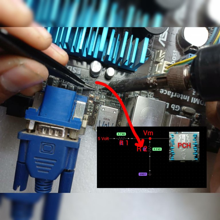
Here I point out where the PCH or Chipset is located, which is under the heat sink shown in the image.
The PCH takes a sample of the 5 volts from the USB ports, through a voltage divider formed by two resistors, in some types of boards the signal is sent to the PCH through a 6-pin integrated circuit, but in my friend's board the sample is taken from a voltage divider formed by two resistors, as I represent in the following illustration.
Here it is observed that to the left of the resistor R1 are the 5 volts from the USB, this resistor forms a voltage divider with R2 which is also connected to ground (GND) and at the point Vm the PCH takes a sample of the 5 volts from the USB, this sample is the voltage that falls on R2.
In these cases in which the problem of the board is due to a misinterpretation of the signal or sample taken by the PCH, it is because one of these resistors (R1 or R2) are in bad condition and therefore the solution lies in finding these resistors and measure the voltage sample that is coming to the PCH, to determine whether it is in parameters or not.
So the thing is to find those resistors on the board, measure the sample or signal taken by the PCH, and determine which of the two resistors is in bad condition.
For this, the following must be known:
The signal or sample that arrives at the PCH should normally be in the order of 3.3 volts, and is measured with a multimeter at the Vm point, if it is well below 3 volts there could be a misinterpretation by the PCH.
To get to this point I will tell you what I did and what you can do if necessary.
Continuing with the methodology the next step would be to identify the resistors of the voltage divider, and to locate them on the board I used the computer application BoardViewer, in which you can visualize the electrical schematic of the motherboard as long as you can download the plan from the internet, also to make use of this program you need a PC or Laptop, this is essential.
This application is an executable so it does not require installation to open it.
Click on file and then on open
Select the motherboard schematic previously downloaded from the Internet and in the format supported by the program, then click on open.
When you open the schematic, it looks like this, where you can see an exact representation of the position of the components on the motherboard, as well as all their structures and connectors.
Because the BoardViewer shows us an exact replica of the physical structure of the board and the position of the components on it, just locate each component on the schematic and look for it on the board.
To speed up the work, in this case, I searched in the search tab of the BoardViewer, the signal that takes the PCH. This signal has different names in the wiring diagrams depending on the type of board and its manufacturer.
For example in the case of MSI boards this signal is named as :
OC#0, OC#1, OC#2, USB_OCP#1,USB_OCP#2, etc..
The manufacturer ASROCK uses on some boards the following names: USB2_OC3#, OC#0123, OC#4567.
GIGABYTE** uses N_USBOC_F, N_USBOC_7, N_USBOC_R, GIGABYTE uses N_USBOC_F, N_USBOC_7, N_USBOC_R, etc..
ASUS uses * S_USB_OC.
If you look closely you will notice that the names are not the same for all the boards but they have something in common in all cases and that is that they all carry the acronym OC (Over Current), so when searching you only have to type the acronym OC in the BoardViewer search tab and you will get the signals that correspond to the different USB that the board presents.
As the board I am talking about is Asus, I have to look for the S_USB_OC signals in BoardViewer, in the tab I show you. It is observed that automatically all the signals of this type come out, that in this board are 7 signals, because there is another one that is not observed in the image.
After locating the signals, the first one is selected and the schematic automatically shows the components where the signal should be measured.
Here are shown in the schematic, marked in yellow the components and pins where the S_USB_OC#12 signal should be measured. Below I show the physical area of the board where these components are located.
This is a better view of the components and the point where you should measure, in this case I pointed it in red in the image of the board, and those are the resistors that form the voltage divider, you should measure with the red tip of the multimeter at the point marked in red.
Here you can see that when selecting the second signal (S_USB_OC#56) two different components are selected, which are the resistors that form the voltage divider, these are 4 resistors of 8.2k in the first component, arranged in horizontal lines and 4 resistors of 4.7k in the second component.
In this way I selected all the signals and the first 6 signals should be measured at the points that I show below.
The red dots represent the pins where the signals that are associated with the USB ports, and that will be interpreted by the PCH, should be measured.
On the right side of the collage are some measurements with the multimeter, and in all cases the voltage was in the order of 3.3 volts, so the 6 signals are in parameters which means that these are not the cause of the problem.
It remains to measure the 7th signal which is named as S_USB_OC#34..
When selecting the signal S_USB_OC#34, the schematic highlights in yellow and red the resistors of the voltage divider, the yellow and red points are common and in any of them the signal can be measured.
Here we can see that the measurement showed a value of 1.68 volt, which means that this is the out-of-parameter signal causing the problem..
This signal at 1.68 volt is due to the fact that one or both of the resistors that form the voltage divider is devalued, so it must be removed and replaced..
Here I am removing the resistor with the help of a soldering iron and a tweezers, this would be R2 in the voltage divider diagram that I showed you before.
When I removed it and measured it with the multimeter I realized that it was devalued, from a value of 8.2k that should have only had approximately 2.3k, which caused the voltage that fell on it was 1.68 volt, causing this small component that the PC was unusable.
After removing the defective resistor, I turned on the PC and automatically the problem disappeared and the power on sequence started correctly, so just removing the resistor is enough to solve the problem, however I had a spare one that I extracted from an old cell phone board.
The first image of the collage shows the spare resistor extracted from a cell board.
The second image shows the resistor soldered on the board.
The third image shows the signal measurement after the replacement, which is at 3.4 volts and therefore in correct parameters, which allows the PC to start up correctly and without problems.
After replacing the resistor, I turned on the PC and this is the result 👇👇
The message disappeared, and the problem was solved, and in the second picture of the Collage you can see that it puts a message related to the bootable device, this means that you need to connect the hard disk to finish with the ignition.
PC running 👌🏼
In this way I solved this fault, which was caused by a tiny resistance but caused a big problem.
I hope this experience will serve at least for knowledge in case the same thing happens to you, of course, I hope you never need to repair your PC, for that give it the maintenance that it takes 😉.
Greetings to you who read me, and until next post 😉.
The images are of my authorship and were taken with a Xiaomi Redmi Note 9 cell phone.
Images edited in the "Gallery" application of the phone and the Photo Collage-GridArt application.
Text translated to English in Deepl translator.
You can see me on Facebook
Esa falla se me presentando y e tirado a la basura varias placas buena iniciativa para reparar estas fallas.
Hola hermano,no puedo creer que las hallas tirado jjj, es que aquí es tan difícil acceder a esos equipos que hasta las placas viejas las recupero para extraer componentes jjj, nada que soy un cacharrero y todo lo quiero guardar pensando que me pueda servir para algo más adelante,😆. Saludos hermano gracias por comentar
Congratulations @darknapol! You have completed the following achievement on the Hive blockchain And have been rewarded with New badge(s)
Your next target is to reach 500 upvotes.
You can view your badges on your board and compare yourself to others in the Ranking
If you no longer want to receive notifications, reply to this comment with the word
STOPTo support your work, I also upvoted your post!
Check out our last posts:
Es un gran post que nos muestra aquí amigo, yo no entiendo mucho de PC pero es muy detallado el paso a paso para descubrir ese tipo de falla y como habilitar de nuevo la PC. Gracias por compartir contenidos de valor, espero algún día coseches en la colmena buenas recompensas por tu trabajo.
Gracias hermano, sí, además de transmitir mis experiencias por si es de ayuda para alguien, también mi objetivo es dejar plasmado en la blockchain estos trabajos que que sirven como base de datos para mi y otra persona que en algún momento lo necesite, la práctica hace al maestro pero cuando se hacen reparaciones a nivel componente en este tipo de placas es bueno tener una base de datos de las diferentes fallas, pues facilita las reparaciones. Saludos hermano y gracias por comentar.
Hola @darknapol excelente publicación, lamento no haberla visto antes, eres buen tecnico, no me imagino lo que harías si tuvieras todo los juguetes (popularismo de mi pais para decir todos los equipos jeje)
Usar el Data sheet habla muy bien de ti, requiere de paciencia, pero hay mayor probabilidad de llegar a la falla, bien ahi.
No te desalientes si tu contenido no cuenta con el apoyo debido, se que es duro trabajar tanto para realizar una publicación de calidad como la tuya y no ser recompensado, todos al principio pasamos por esto, mi recomendación, no te quedes en un solo nicho, yo tuve que reinventarme porque mis publicaciones eran muy parecidas a esta cuando empece, asi que luego empecé a publicar de películas, juegos y hasta cocina, porque las personas que entienden este tipo de contenido técnico son escasas y no lo valoran, al final hive debe ser una ayuda económica, se constante y mantente dentro de los parámetros, nunca plagies, se autentico y veras los resultados, animo amigo.
Hola amigo @danielcarrerag, gracias por tus palabras, ciertamente sueño con tener un días mis jugueticos 😂, la verdad hay muchos que me harían las reparaciones mucho más fáciles, pero bueno todo llega poco a poco. Entiendo tu consejo sobre abarcar otros temas , intentaré hacerlo pero la verdad si me apasiona leer contenidos sobre cuestiones técnicas, pero no quiere decir que no me gusten otros temas, así que siempre que pueda probaré otras direcciones. Una vez más te agradezco por tus consejos los tendré siempre en cuenta. Gracias hermano, Saludos